PAGE
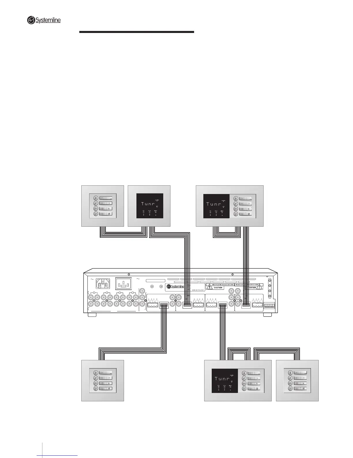
4.3 Zone Connection
Strategies
a) Each zone will support two DMSs and
three KMSs. All the command devices for
one zone should connect to each other in
serial fashion using their appropriate
circuit board-mounted “In” and “Out”
terminals.
b) Each DMS signals when it receives and
processes a command. This happens
regardless of whether the command was
generated by a keypad or a hand held
remote. However, a keypad located
“downstream” of a DMS module will
not
trigger that sensor’s command
processing indicator.
Whenever possible, we suggest that you
always wire a DMS/KMS double wall box
so that the DMS is located “downstream”
from the adjacent KMS (i.e., between the
KMS and the S4.3 Controller). This
ensures that the DMS module always
signals the user when the adjacent
keypad is used.
Whenever possible, we suggest that you
configure each combined DMS and
keypad module, with the 'Out' of the
keypad connecting to the 'In' on the DMS.
Section 4 • Installation Guide
4
3
2
DATA
DATA
RC-5
N/C
AUDIO IN
AUDIO
OUT
IN
RIGHT
INPUTS
LEFT
OUT IN
OUT
IN
OUT
IN OUT
ZONE B
SPEAKERS
RIGHTLEFT
DATA
ZONE C
WE1
WE2
WE3
WE4
TX-FORMAT
ZONE A
SPEAKERS
RIGHT
LEFT
SPEAKERS
RIGHTLEFT
SPEAKERS
RIGHT
LEFT
DATA
T
X
O
U
T
P
U
T
S
1
ZONE D
S4.3 MUTI-ROOM CONTROLLER
CONTROL
LINK
IN OUT
230V AC
50Hz
POWER CONSUMPTION: 430W MAX
PRE/LINE-OUTPRE/LINE-OUT
PRE/LINE-OUT
PRE/LINE-OUT
TRIGGER
PAGING
AC OUTLET
230V 50Hz
SWITCHED TOTAL:
460W MAX
123456
123456 123456 123456
123456
OUT
OUTOUT
OUT
IN OUT IN
OUT
IN
OUT
IN
OUT
19