PAGE
4.2 Zone Control Devices
4.21 DMS Module
PLACEMENT SUGGESTIONS: Exact
placement will vary with each installation
but we strongly recommend AGAINST
placement where the DMS will be
exposed to direct sunlight, powerful
fluorescent illumination or the output of a
high intensity spotlight, etc. These light
sources contain high levels of infrared
energy themselves and may cause
intermittent operation by saturating the
DMS.
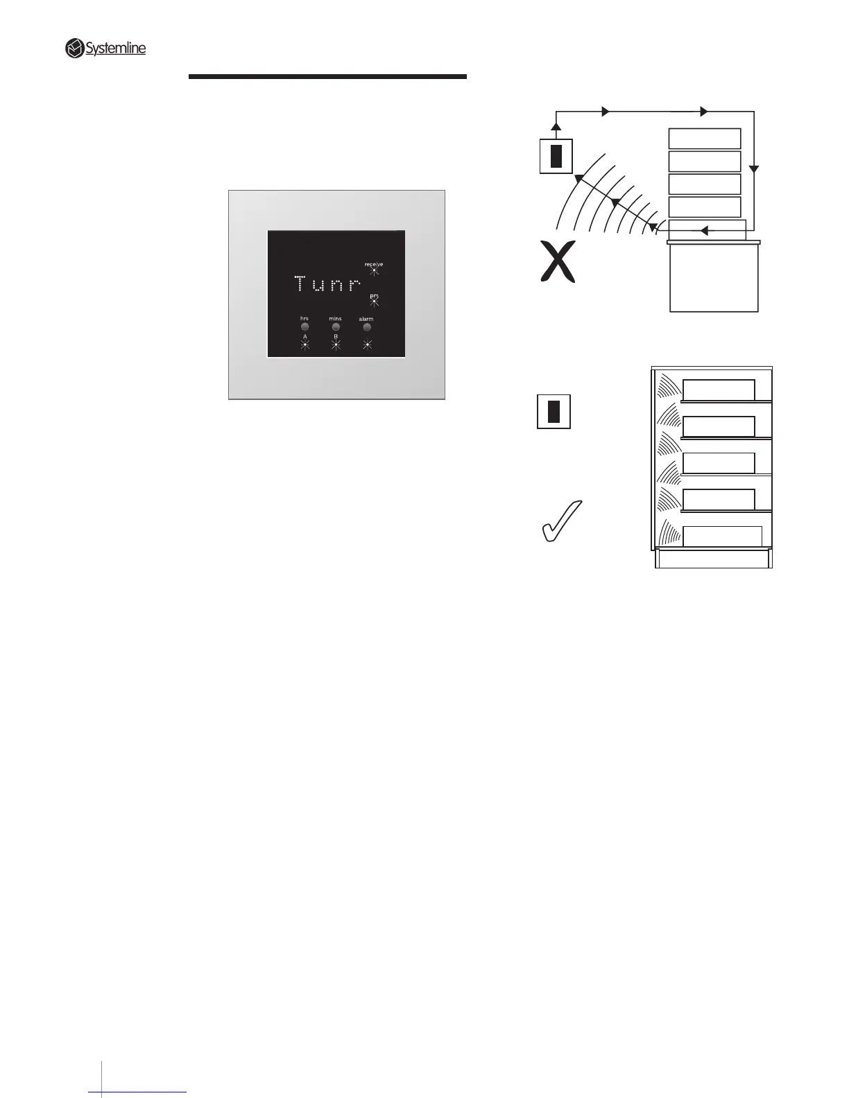
Also, avoid infrared “loops” by making
sure that a DMS module is
not
placed
where it might pick up signals from a
source component’s IR repeater or the
S4.3 Controller’s IR “flood” emitter.
Lastly, make sure that each DMS is on a
relatively uninterrupted “line-of-sight”
path to all likely locations from which the
hand held RHS remote might be used.
You’ll find the DMS/RHS combination
much less susceptible to signal
interference than other IR remote control
links but conservative planning will
ensure dependable operation under an
even wider variety of conditions.
Each DMS module has eight DIP switches
positioned centrally on the internal circuit
board and accessed by removing the
housing rear cover.
Section 4 • Installation Guide