TAC AB, 2001-08-08 0-004-7506-4 (EN), 11 (36)
TAC Xenta OP Handbook 2 Connection and Basic Functions
2.3 Connecting to TAC Xenta 300/401
Cable between controller and Operator panel...................... max. 10 m
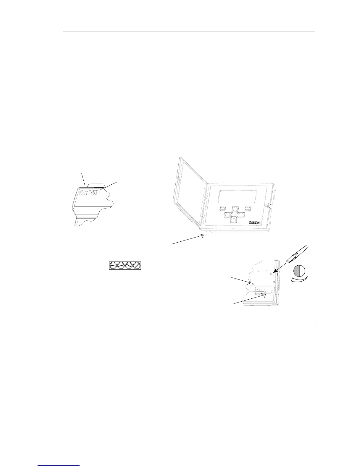
When connecting the operator panel there are two alternatives (please
refer to the adjacent figures):
• Use the modular socket on the front of the TAC Xenta 300 or 401
controller and the corresponding socket on the back of the operator
panel. This requires a special cable.
• Use the screw terminals on the back of the operator panel, la-
belled 1–4. Terminals 1 and 2 are used for communication and
terminals 3 and 4 for 24 V AC (or DC).
At the controller you use the terminals C1, C2 and G, G0.
TAC Xenta 300/401
controller
TAC Xenta OP connectors and contrast potentiometer
Contrast
adjustment
(on the rear)
The contrast of the display can be adjusted with the potentiometer on
the rear of the operator panel.
(The Service pin is available from the rear if, in special cases, the
network configuration procedure requires this. When the pin is
pressed, a unique hardware identity code is sent on the network.)
Socket for
connection to the
operator panel
Socket and screw terminals for
the TAC Xenta controller
connection
4
3
21
C1 C2 G G0
Service pin
Modular socket
on the OP
 Loading...