TAC AB, 2001-08-08 0-004-7506-4 (EN), 9 (36)
TAC Xenta OP Handbook 2 Connection and Basic Functions
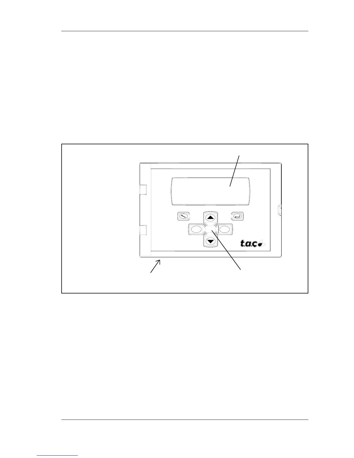
The TAC Xenta OP operator panel
LCD display
Connectors
(rear)
Push buttons
+
–
2 Connection and Basic Functions
2.1 Description
The TAC Xenta OP Operator panel has an LCD display with 4*20
characters and six push buttons. A modular socket or four screw
terminals are used for communication and for connecting the power
supply. These connectors are placed on the rear. There is also a
potentiometer to adjust the contrast of the display, on the rear.
The OP has an LCD display that can be lighted from beneath. The
light is controlled from the OP Service menu (section 2.5).
The operator panel is used to monitor status and to adjust setpoints
and time channels. It also makes it possible to list the alarms without
communicating with a central system.
The operator panel is controlled from a master, a TAC Xenta 100, 300
or 401 controller. When you start using the operator panel, it will send
a message to the master telling it what button was pushed. The master
contains the dialogue messages and will direct the operator panel what
to show on the display. Thus the operator panel will act as a dumb
terminal.
 Loading...