TMA Q Series Getting Started Guide
26
Connecting Cables and Lines
To connect the cables and gas lines, you will need access to the TMA instrument’s rear panel. All directional
descriptions are written on the assumption that you are facing the back of the instrument.
NOTE: Connect all cables before connecting the power cords to outlets. Tighten the thumb-
screws on all computer cables.
CAUTION: Whenever plugging or unplugging power cords, handle them by the plugs,
not by the cords.
WARNING: Protect power and communications cable paths. Do not create tripping
hazards by laying the cables across accessways.
WARNING: DO NOT position the instrument so that it is
difficult to turn off the power switch or to unplug the power cord.
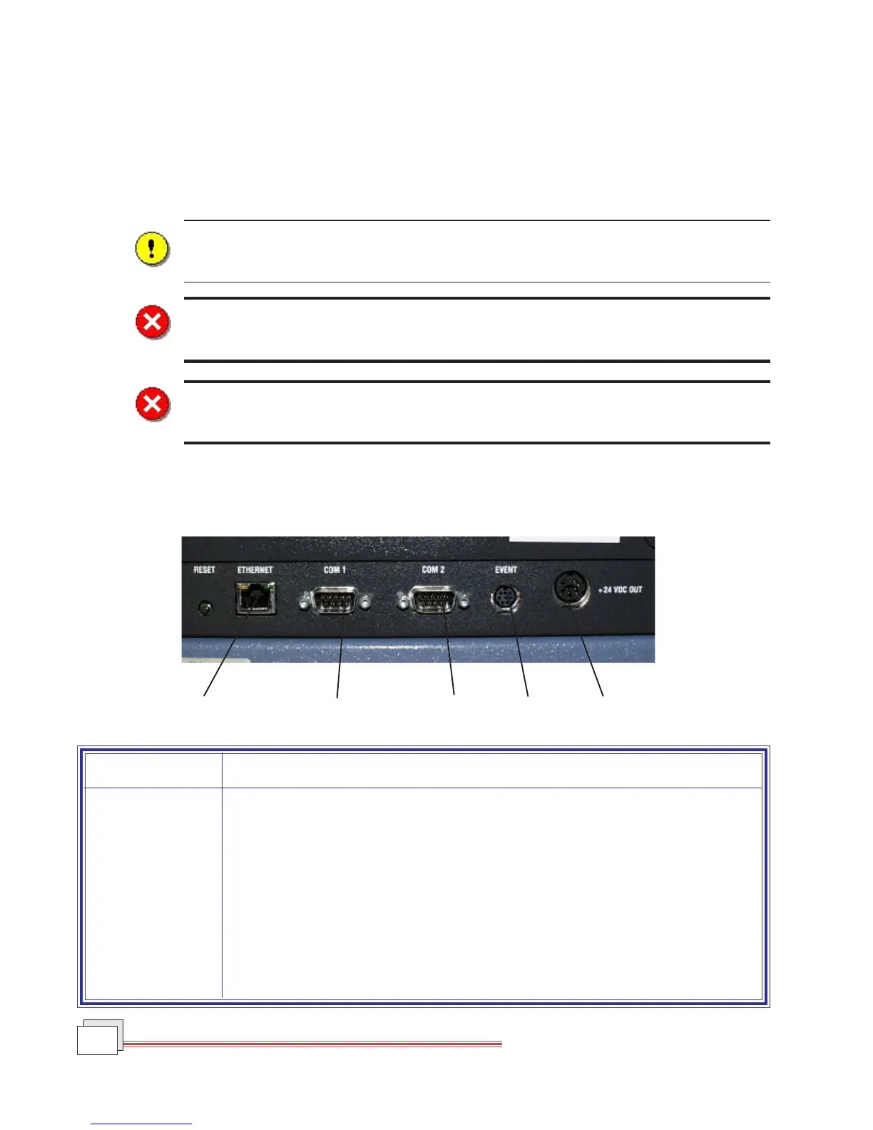
Ports
The TMA has nine ports that are located on the back of the instrument. The following table provides a descrip-
tion of function of each port. Refer to this list when connecting cables and lines.
Port Function
Ethernet Provides communication capabilities.
Com 1 Diagnostic port (factory use only).
Com 2 Accessory port.
Event Capable of the following functions: general purpose relay contact closure, or
general purpose input 4 – 24 Vdc for external syncing. This port is not used for
standard operation.
24 VDC output This port is not used with the TMA.
(table continued)
Five Ports on Left Rear of TMA
Ethernet
COM 1
COM 2
Event
24 VDC Output
 Loading...