Instruction and Operating Manual
TA-U1...U280
Misprints and technical changes reserved
18
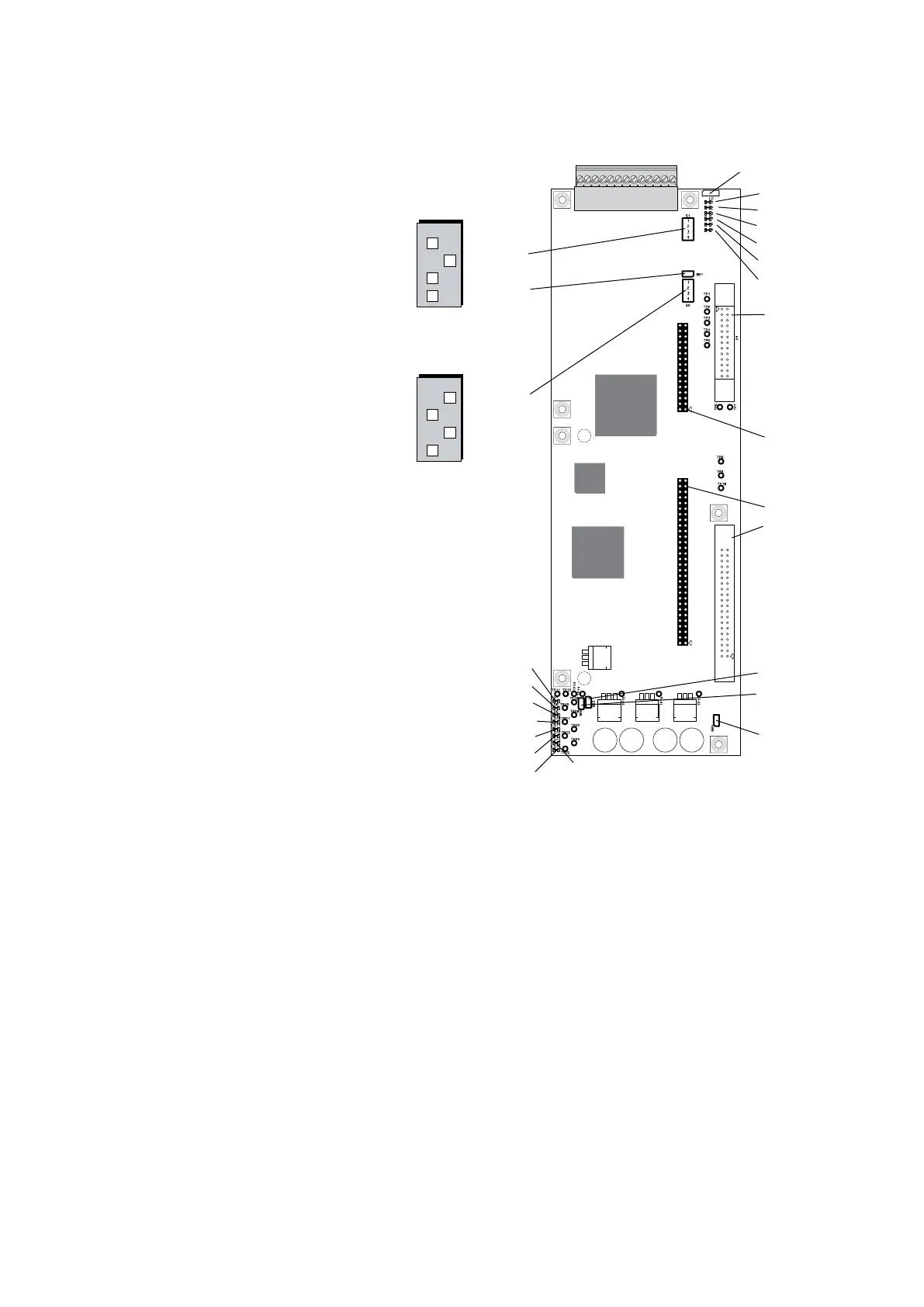
3.3.6 Controlboard TA-U1...U150
X1 Connection to powerstage
X2 Connection to Digital - Analogboard,
bussystems and Ethernetboard
X4 Connection to displayboard
X5 Connection to Encoderboard
S1 Configuration of digital and anlog
connections
S2 Configuration of processor
BR1 Reset µC
BR2 Real time clock active
BR3 Reset DSP
BR4 Common connection, connected to
ground with 100R (or 1MR)
BR5 Digital output terminal 12,13,
(refer to chapter 5.2)
Pin 1-2 closed: closing contact
Pin 2-3 closed: opening contact
LD1 Yellow - Input terminal 2
LD2 Yellow - Input terminal 3
LD3 Yellow - Input terminal 4
LD4 Yellow - Input terminal 5
LD5 Yellow - Output terminal 10/11
LD6 Yellow - Output terminal 12/13
LD7 Green - +3,3V
LD8 Green - +1,9V
LD9 Green - +24V
LD10 Green - +3,3V
LD11 +2,5V
LD12 Green - +6,5V
LD13 Green - -24V
LD14 Green - +5V
X2
X5
5
4
1
2
3
6 12
9
10
8
11 13
X4
X1
7
LD1
LD2
LD3
LD4
LD5
LD6
X4
X5
X2
X1
LD7
LD8
LD9
LD10
LD11
LD12
LD14
BR4
S1
BR1
S2
BR
LD13
ONOFF
4
3
2
1
DIP switch S1
(Factory adjustment)
00 0
1
ONOFF
4
3
2
1
DIP switch S2
(Factory adjustment)
0
11
0
BR5