EasyManua.ls Logo

tae TA-U65 HT

Default Icon
86 pages
To Next Page IconTo Next Page
Loading...
State 09-2016 V-1 TA-U1_U280-e.indd The German text applies in cases of doubt
TA-U1...U280
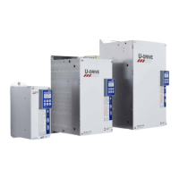
Universal Antrieb / Universal Drive
Instruction and Operating Manual
Pikatron GmbH • division TAE Antriebstechnik • Raiffeisenstrasse 10 • D-61250 Usingen

Table of Contents

Questions and Answers:

tae TA-U65 HT Specifications

General IconGeneral
Brandtae
ModelTA-U65 HT
CategoryDC Drives
LanguageEnglish

Summary

2. Instructions of Safety

2.2 Safety

General safety precautions for handling electrical equipment.

3. Description of the Product

3.2 Technical Data

Specifications, part numbers, dimensions, and current derating.

3.3 Printed Circuit boards & modules

Details on various PCB modules and their functions.

4.0 Setting up

4.1 Setting up instructions

General instructions for installation and wiring.

5.0 Connections

5.1 Power Connections

Details on connecting the main power supply to the drive.

5.2 Connection Diagram Controlboard

Diagram showing control board connections for standard configuration.

6.0 Operation

6.1 Instructions of Safety

Safety instructions relevant to operating the drive.

6.2 Setting Motor Parameters

Procedure for configuring motor parameters for optimal performance.

7.0 Troubles

7.2 Fault Description

Lists and explains potential error codes and fault indications.

2. General

2.1 Name Plate

Information printed on the device label for identification.

3.1 Introduction

3.1.2 Protection Against Irregular Usage

Warnings against incorrect application of mains voltage to output terminals.

3.2.1 Drive Specifications - Part numbers TA-U1...U280

3.2.2 Dimensions TA-U2... U400

Physical dimensions of drive units from TA-U2 to TA-U400.

3.2.3 Device data and Dimensions

3.2.4 Rated current de-rating in relation to switch frequency

3.3 Printed Circuit boards & modules

3.3.1 Powerstage TA-U1..U6

Details and diagram of the power stage for TA-U1 to TA-U6 models.

3.3.2 Powerstage TA-U8..U15

3.3.3 Powerstage TA-U22..U90

3.3.4 Powerstage start at U110

3.3.5 Printed circuit boards modules TA-U1...U150

3.3.6 Controlboard TA-U1...U150

3.3.7 Encoderboard Standard

3.3.8 Encoderboard RS422

3.3.9 Encoderboard Resolver 0403 (12 Bit)

3.3.10 Encoderboard Resolver 0406 (16 Bit)

3.3.11 Encoderboard SinCos

3.3.12 Digital - Analog board

3.4 Principle Diagrams

4.1 Setting up instructions

4.1.2 Arrangement of Wires

Guidelines for routing and separating power and control cables.

4.1.3 Conditions for Grounding

4.1.5 Instruction for Mounting

4.1.6 Arrangement in Switch Cabinet

Guidelines for spacing and cable management within a switch cabinet.

5.1 Power Connections

5.2 Connection Diagram Controlboard

5.2.1 Connection Diagram Controlboard standard

Standard wiring diagram for the control board and digital inputs.

5.2.2 Connection Diagram Controlboard save Torque

5.3 Connection Diagram Encoders

5.4 Connection Diagram Analog - Digital upgrading

6.2.2 Setting of Motor Parameters

6.2.3 Functional Tests and Initial Operation

7.2 Troubleshooting

7.2.1 Sensor test

Procedure to test the motor sensors (U, V, W, A, B) using LED indicators.

Appendix 1 list of Parameters

02: Motor Data

03: Drive Data

05: SpeedCurrent

06: Ramps

07: Control Dynamics

08: Digital IO

09: Analog IO

10: PLC IO

11: Monitoring-Limits

Drive Over-Temp Limit

Sets the temperature limit for drive over-temperature protection.

12: Actual Values

13: CommandStatus Words

14: Error-Status

15: Communication

16: MasterSlave

17: Motorpotentiometer

18: Positioning

Positioning Control

Controls various positioning tasks and parameters.

20: Brake Systems

Brake System Control

Controls the activation and feedback of the brake system.

21: Keypad PG4000

22: Error Log

23: Trace

Parameters

Selecting parameters

Related product manuals