TA-U1...U280
Instruction and Operating Manual
Misprints and technical changes reserved
19
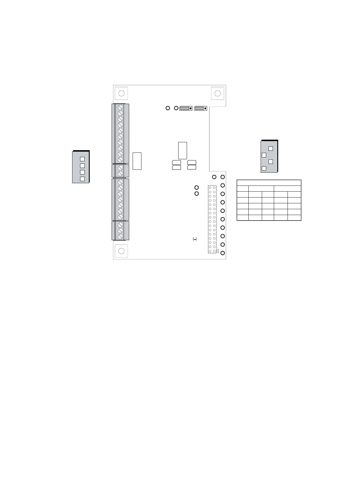
3.3.7 Encoderboard "Standard"
X5 Connection to controlboard
S1 GND Connections of the input terminals
34,36 and 39 (Z,/Z,AB)
S2 Voltage or frequency track AB
BR1 Frequency output terminal 41, track B
Pin 1-2 closed: actual speed value,
factory adjustment
Pin 2-3 closed: special
funktion
BR2 Frequency output terminal 40, track A
Pin 1-2 closed: actual speed value,
factory adjustment
Pin 2-3 closed: special funktion
BR3 Motor temperature sensor terminal 21
open: thermo switch and PT100
closed: KTY and PTC
BR4 Motor temperature sensor terminal 22
open: thermo switch and PT100
closed: KTY and PTC
BR5 Motor temperature sensor terminal 21
open: thermo switch and PT100
closed: KTY and PTC
BR6 Motor temperature sensor terminal 22
open: thermo switch and PT100
closed: KTY and PTC
LD1 Green - +5V
42
41
39
38
37
36
35
34
33
32
31
30
29
28
27
26
25
24
23
22
21
40
TP1 TP2
4
3
2
1
S2
4
3
2
1
S1
TP3 TP4
TP5
TP8
TP9
TP10
TP11
TP12
TP13
TP14
TP15
TP6
TP7
X5
LD1
Encoder Standard 0401
BR1 BR2
DIP switch S1
(Factory adjustment)
refer to chapter 5.3.1
OFFON
1
2
3
4
DIP switch S2
(Factory adjustment)
1
00
1
OFFON
1
2
3
4
00 00
Speed actual value track AB
S2
3
2
1
4 OFF
OFF
5V 24V
ON
ON
DIP Voltage Impuls/UPM
ON
ON
<100 >100
OFF
OFF
BR4
BR6BR5
BR3
1
2
3
1
2
3
Ilustration of Jumper BR on board, is factory adjustment