TB9100 Reciter Service Manual RF Circuitry 87
© Tait Electronics Limited January 2006
6 RF Circuitry
6.1 Receiver RF Circuitry - VHF Reciter
6.1.1 Front End
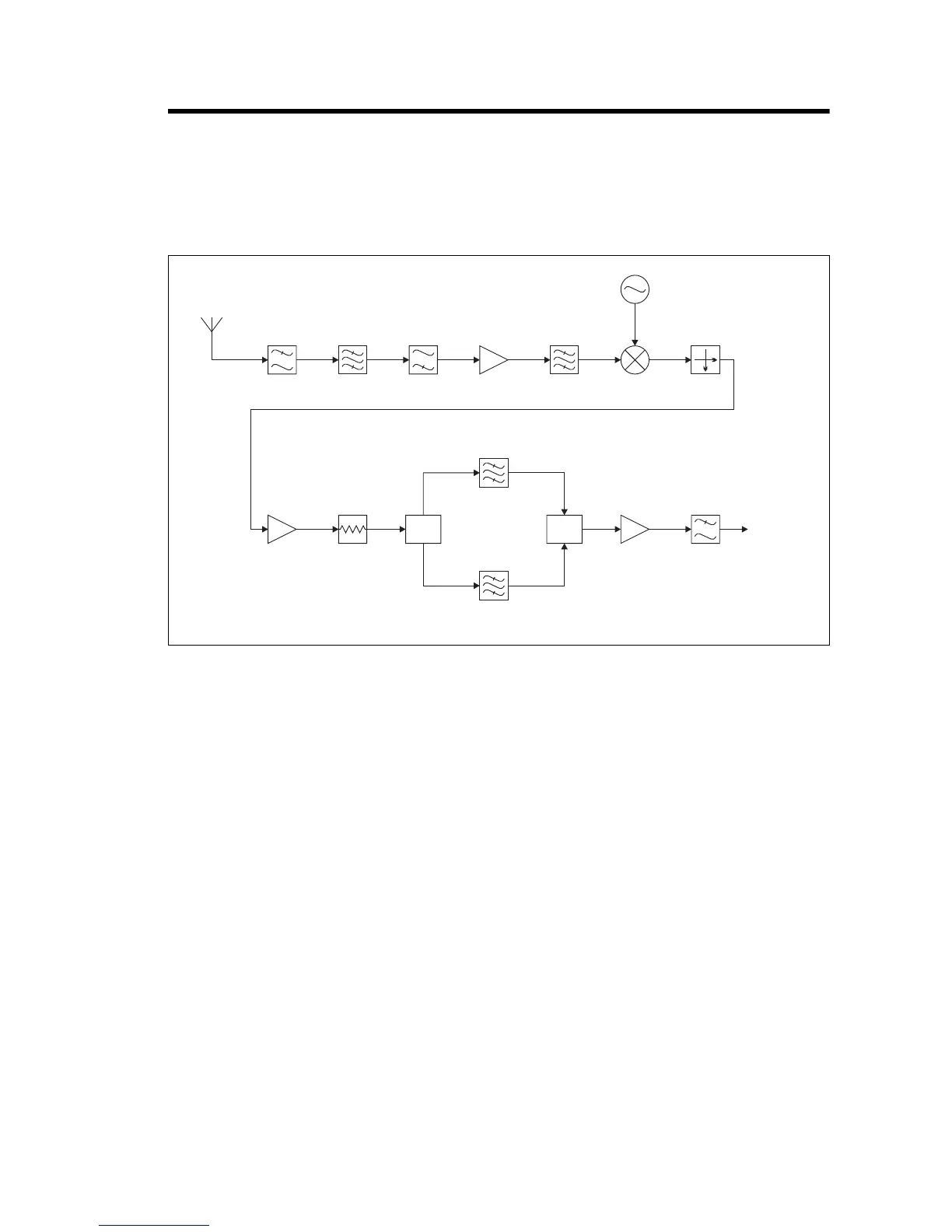
The incoming signal from the BNC connector is fed through a low pass
filter, then through a band pass “doublet” filter, and finally through a high
pass filter. These networks attenuate harmonics and spurious responses.
The signal is then amplified and passed through another band pass “doublet”
filter before being passed to the mixer.
6.1.2 Mixer
The RF signal from the front end is converted down to the 16.9MHz IF by
a high level (+17dBm local oscillator) mixer. The voltage controlled
oscillator (VCO) generates a level of 20dBm which is fed to the mixer
through an attenuator pad. A diplexer terminates the IF port of the mixer in
50Ω, thus ensuring a good match for all mixing products, as well as
enhancing the linearity. The post-mixer buffer amplifier provides gain and
isolation between the mixer and crystal filter. It also compensates for the
insertion loss of the crystal filter.
Figure 6.1 Reciter VHF Receiver RF Circuitry Block Diagram
Band Pass
Filter 1
Band Pass
Filter 2
RF
Amplifier
Low Pass
Filter
High Pass
Filter
Attenuator
Pad
Mixer
Local Oscillator
Diplexer
Post-mixer
Buffer
Narrow Bandwidth
Crystal Filter
Wide Bandwidth
Crystal Filter
IF
Amplifier
Anti-alias
Filter
IF Output
RF In
Switch Switch
 Loading...


