122 Technical Description TB9100/P25 CG/P25 TAG Installation and Operation Manual
© Tait Limited March 2014
■ Reciter temperature
■ Fan on/off state
■ Fan rotation state (the fan must have a 3-wire connection to detect
rotation, as well as power and ground)
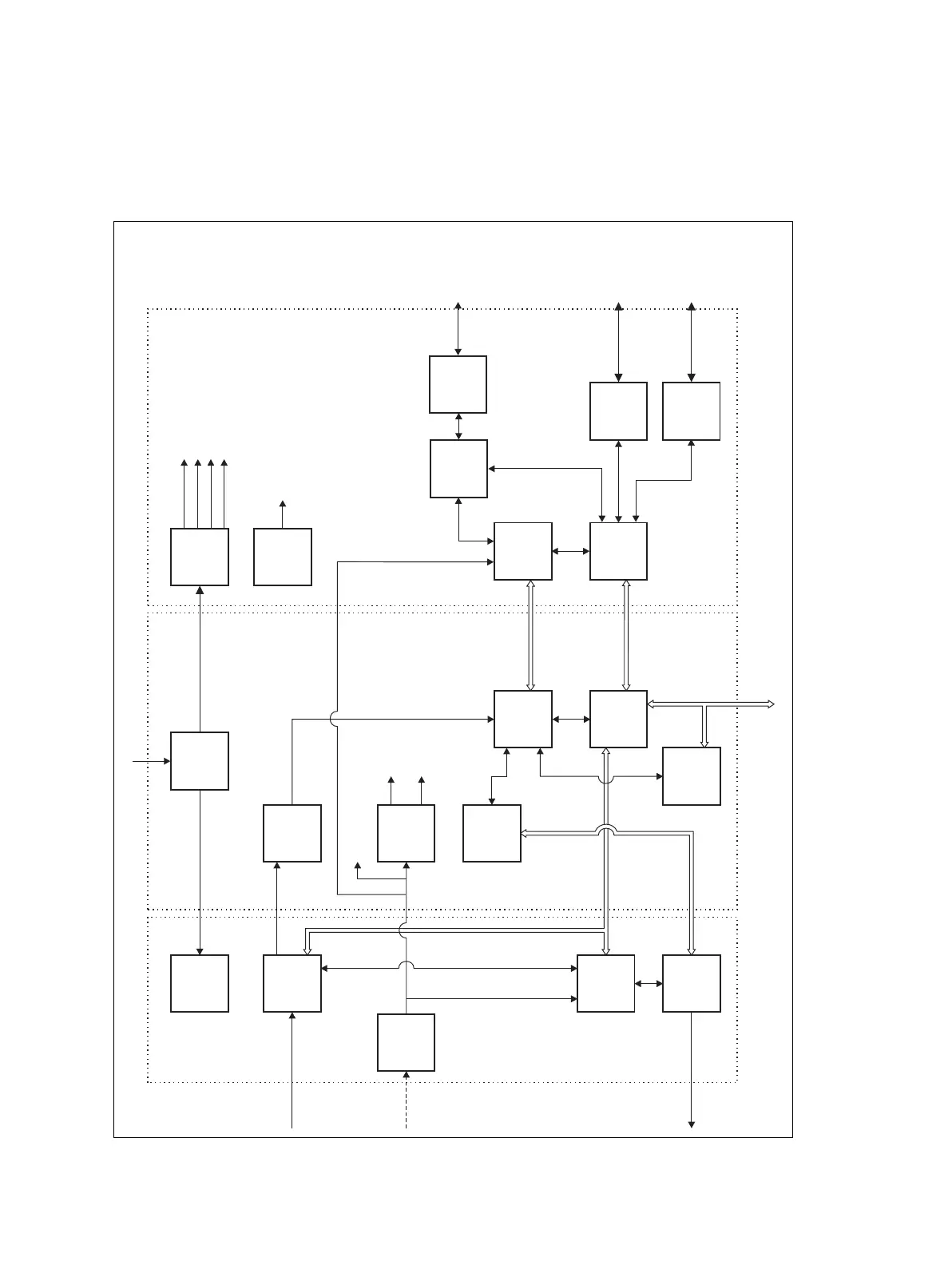
Figure 8.3 Reciter high-level diagram
DSP
CODEC
CODEC
CODEC
40MHz
Clock
Receiver
Exciter
Synthesizer
Subsystem
Reference
Frequency
Subsystem
Digital
Receiver
Power
Supply
Power
Supply
RISC
DSP/RISC
13MHz
Clock
RISC
CODECs
IF
12.8MHz
Ref.
RF I/P
28VDC I/P
28V
28V
RF O/P +
PA Key
Audio
System
Control Bus
Digital
Receiver
Control &
Communications
Control &
Communications
Control &
Communications
Host Port
Interface
Host Port
Interface
Modulation
& Frequency
Control
Control &
Communications
External
Reference
Frequency
(if used)
RF Board
Digital Board
Power
Supply
Network Board
3.3V
6V
1.6V
1.8V
Digital I/Os & Audio/E&M Subsystem
DSP/RISC I/O Drivers & Memory
DSP
RISC
DSP
RISC
Audio/
E&M
Subsystem
Ethernet
Subsystem
RS-232
Subsystem
Digital Channel
Group Interfac
RS-232 +
Digital I/O
Analog
Line
 Loading...


