TB9100/P25 CG/P25 TAG Installation and Operation Manual Technical Description 117
© Tait Limited March 2014
8 Technical Description
8.1 Mechanical Assembly
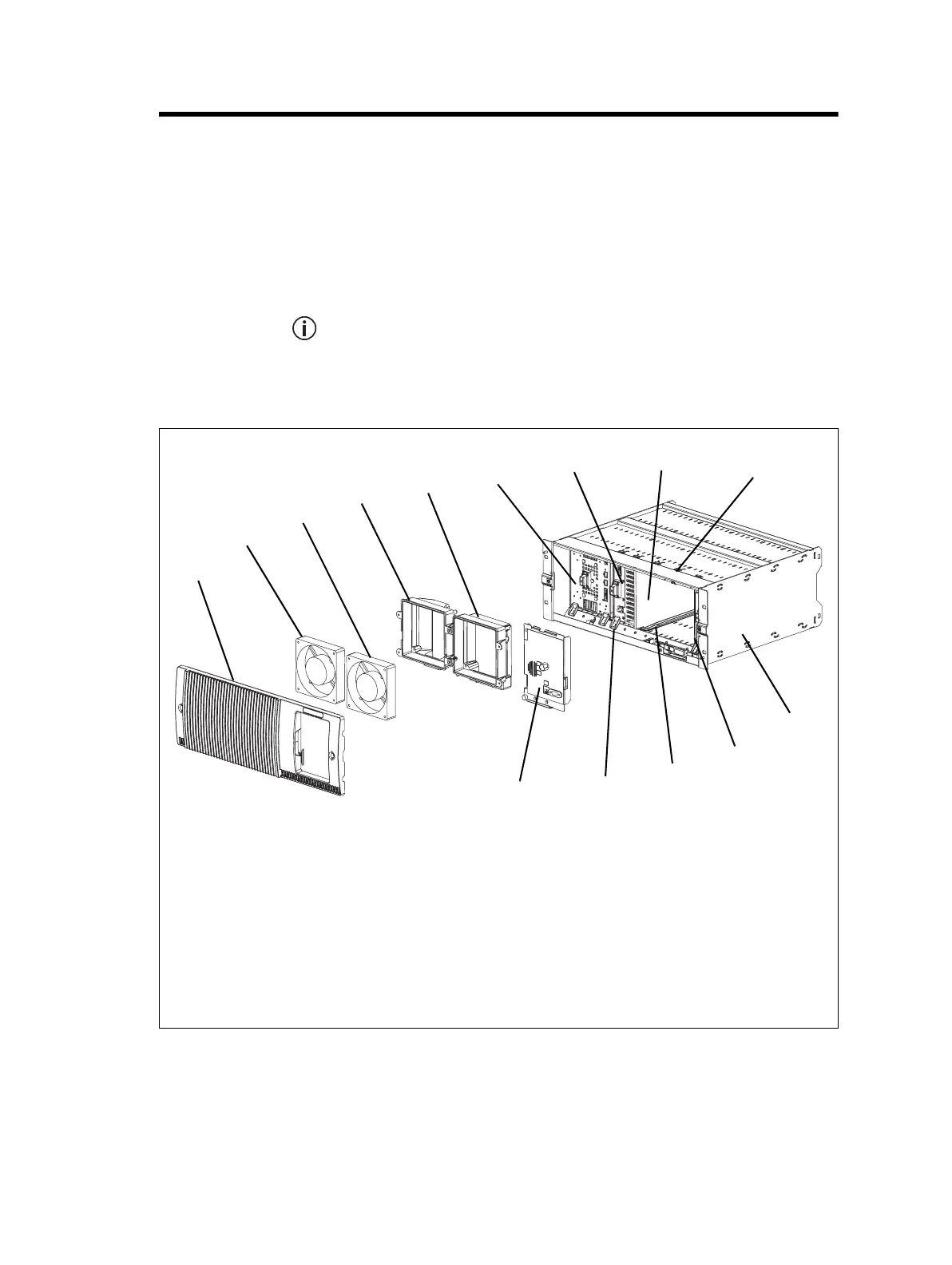
This section illustrates the main mechanical components that comprise the
base station. Figure 8.1 below shows the configuration for a typical 5W or
50W base station.
Figure 8.1 shows the cooling fans and their ducts detached from the front
panel only for the clarity of the illustration. The cooling fans and ducts
are normally screwed to the rear of the front panel.
.
Figure 8.1 Mechanical assembly - front panel, fans and control panel
b
front panel
i
airflow separator
c
PMU fan
j
cable retaining clip
d
PA fan
a
1)
subrack
e
PMU fan duct
1!
reciter
f
PA fan duct
a
1@
plastic guide rail
g
PMU
1#
module retaining clamp
h
PA
a
1$
control panel
a. Not present in a gateway.
b
c
d
e
f
g
h
i
j
1)
1!
1@
1#
1$
or
ase stat
on s
own

 Loading...


