TB9100/P25 CG/P25 TAG Installation and Operation Manual Replacing Modules 99
© Tait Limited March 2014
3. Insert the securing screw into the floating nut i in the subrack and
tighten. Note that you may have to push the screw in and down to
pick up the floating nut.
4. Carry out the instructions in “Final Reassembly” on page 115.
Configuring the Control Panel Board
A link (J300) is provided on the control panel board which allows you to
select the color displayed by the seven channel LEDs (refer to the examples
below). This link selects the color for all the channel LEDs.
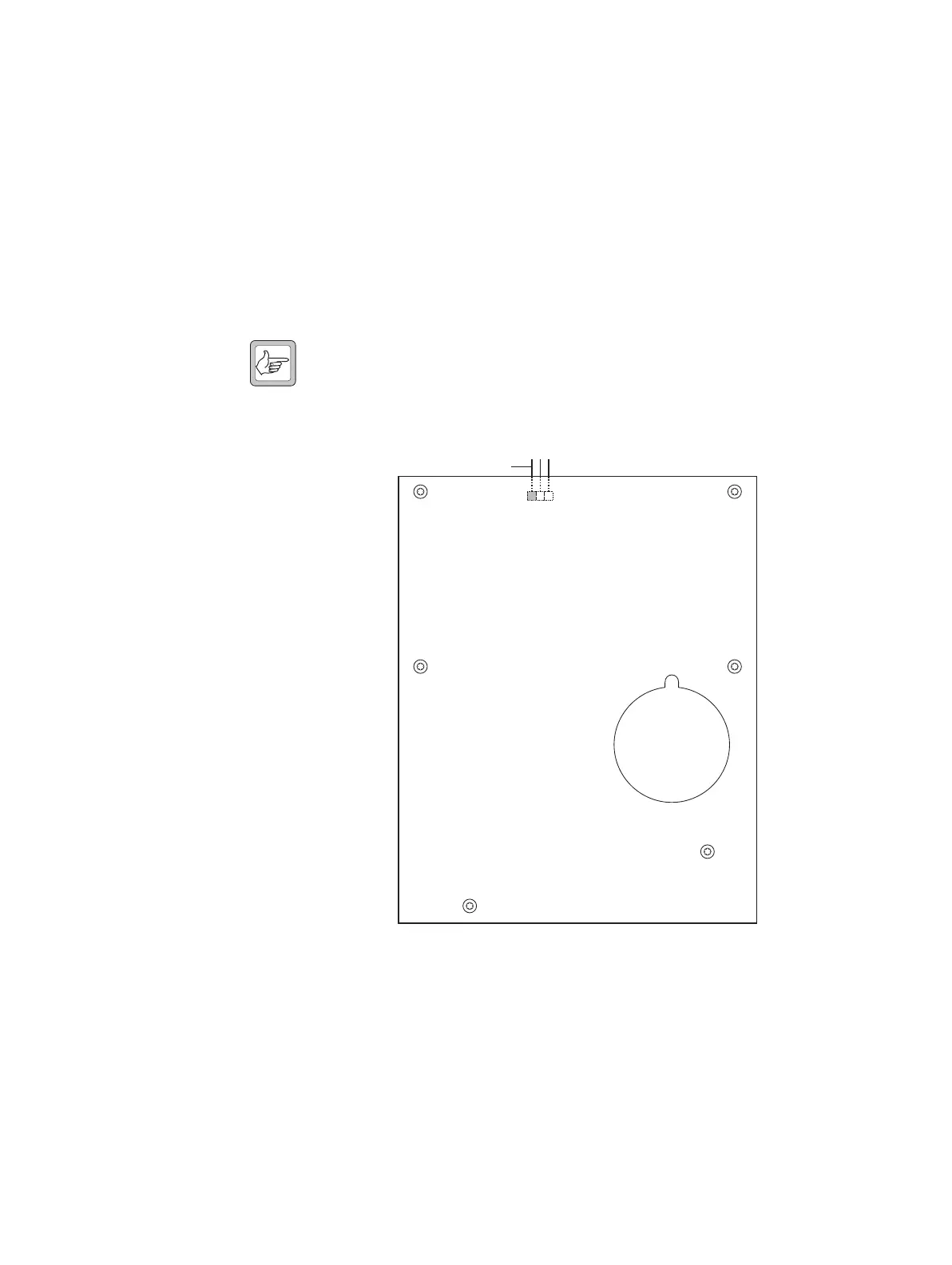
Note The following diagram shows the bottom side of the board (as
seen with the board mounted in the control panel chassis). J300 is
mounted on the top side of the board, and is accessible from the
top of the control panel assembly.
Examples of LED
Colors
Example 1
With the following link settings:
■ Subrack interconnect board links set for Rx gate status signal (see
“Configuring the Subrack Interconnect Board” on page 112)
■ control panel board link across pins 1 and 2
J300
pin 1
J300
 Loading...


