142 Appendix B – Inter-Module Connections TB9100/P25 CG/P25 TAG Installation and Operation Manual
© Tait Limited March 2014
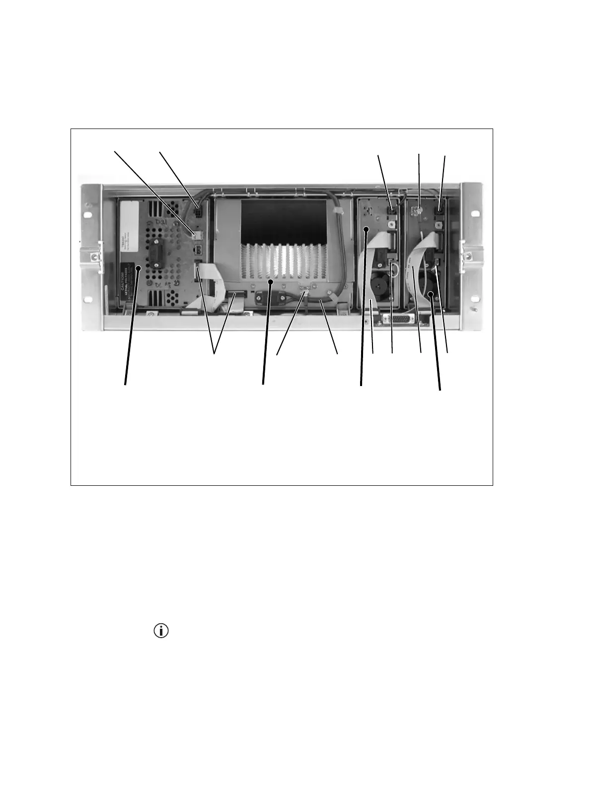
100W Base Station
The connections between modules at the front of a 100W base station are
shown below.
Notice The PMU must be connected to the system control bus at all
times. The terminating circuitry for the bus is located in the PMU, and
if the PMU is disconnected, the state of much of the bus will be unde-
fined. This may cause corrupted data to be present on the bus when the
reciter reads the states of the switches on the control panel. This in turn
may result in random actuations of microphone PTT, carrier, or speaker
key, causing the base station to transmit or the speaker to be actuated
incorrectly.
The above illustration is an example of a 100W base station with two
reciters. However, the second reciter is not a requirement of a typical
100W base station.
100W base station internal connections
b
28VDC high current output for PA
f
DC output for reciter fan
c
28VDC low current output for reciter
g
system control bus
d
28VDC low current input from PMU
h
28VDC high current input cable from PMU
e
RF output to PA
i
RF input from reciter
bc
d
e
h
f
g
f
i
PA reciter 2
PMU
g
reciter 1
d
g
 Loading...


