TB9100/P25 CG/P25 TAG Installation and Operation Manual Replacing Modules 103
© Tait Limited March 2014
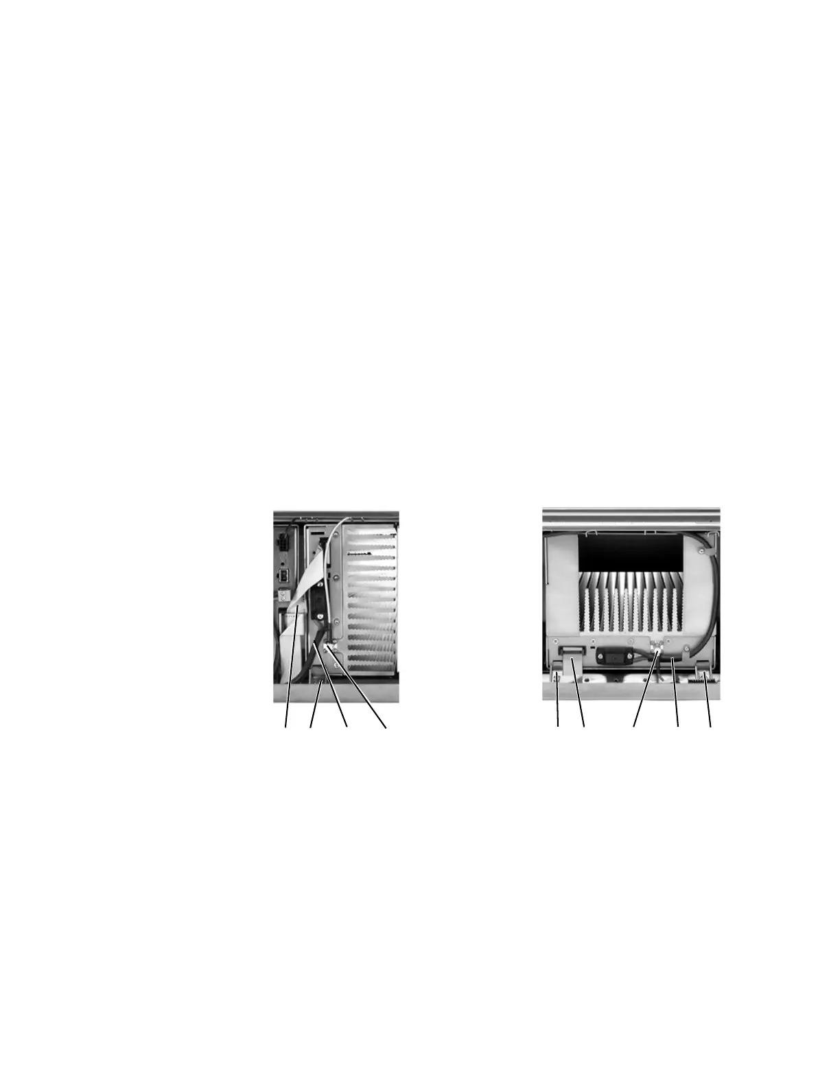
7.5 Replacing a Power Amplifier
Notice Before removing a PA, disconnect the DC input and RF input
first, followed by the RF output (and DC output on the 12V PA). After
refitting the PA, reconnect the RF output (and DC output on the 12V
PA) first, followed by the RF input, and then the DC input.
Removal 1. If you have not already done so, carry out the instructions in “Pre-
liminary Disassembly” on page 96. If necessary, remove the control
panel, as described in “Replacing the Control Panel” on page 98.
2. At the front of the PA, unplug the DC input cable (DC output cable
on the 12V PA)
b and the RF input cable c, and move both cables
to one side. Unplug both ends of the system control bus loom
d and
remove it.
3. At the rear of the PA, unplug the RF output cable. 12V PA only:
also unplug the battery supply lead.
4. Loosen the screw securing the retaining clamp(s)
e and rotate the
clamp(s) through 90° to clear the module.
5. Slide the PA out of the subrack, taking care not to damage any of the
cables.
Refitting 1. Slide the replacement PA into the subrack and secure it with the
retaining clamp(s).
2. At the rear of the PA, connect the RF output cable.
12V PA only:
Also connect the battery supply lead. Tighten the screws to a torque
of 4.5lbf·in (0.5N·m).
3. At the front of the PA, connect the RF input cable, followed by the
DC input cable (DC output cable on the 12V PA).
b
e
c
b
d
dec e

 Loading...


