118 Technical Description TB9100/P25 CG/P25 TAG Installation and Operation Manual
© Tait Limited March 2014
The front panel can be easily removed from the subrack by undoing two
quick-release fasteners. Once the front panel is removed, the control panel
can also be removed from the subrack by undoing a single screw. Refer to
“Replacing Modules” on page 95 for more details.
The PMU occupies the slot at the left end of the subrack, with the PA beside
it. The reciter normally occupies the slot at the right of the subrack
(position 1).
The PA is mounted vertically with the heatsink facing the center of the
subrack. This positions the cooling fins directly behind the PA fan. The
airflow separator is fitted directly beside the PA to help direct the cooling
airflow through the heatsink.
The configuration for 12V base stations is the same as shown in
Figure 8.1, but the PMU and its cooling fan are not fitted.
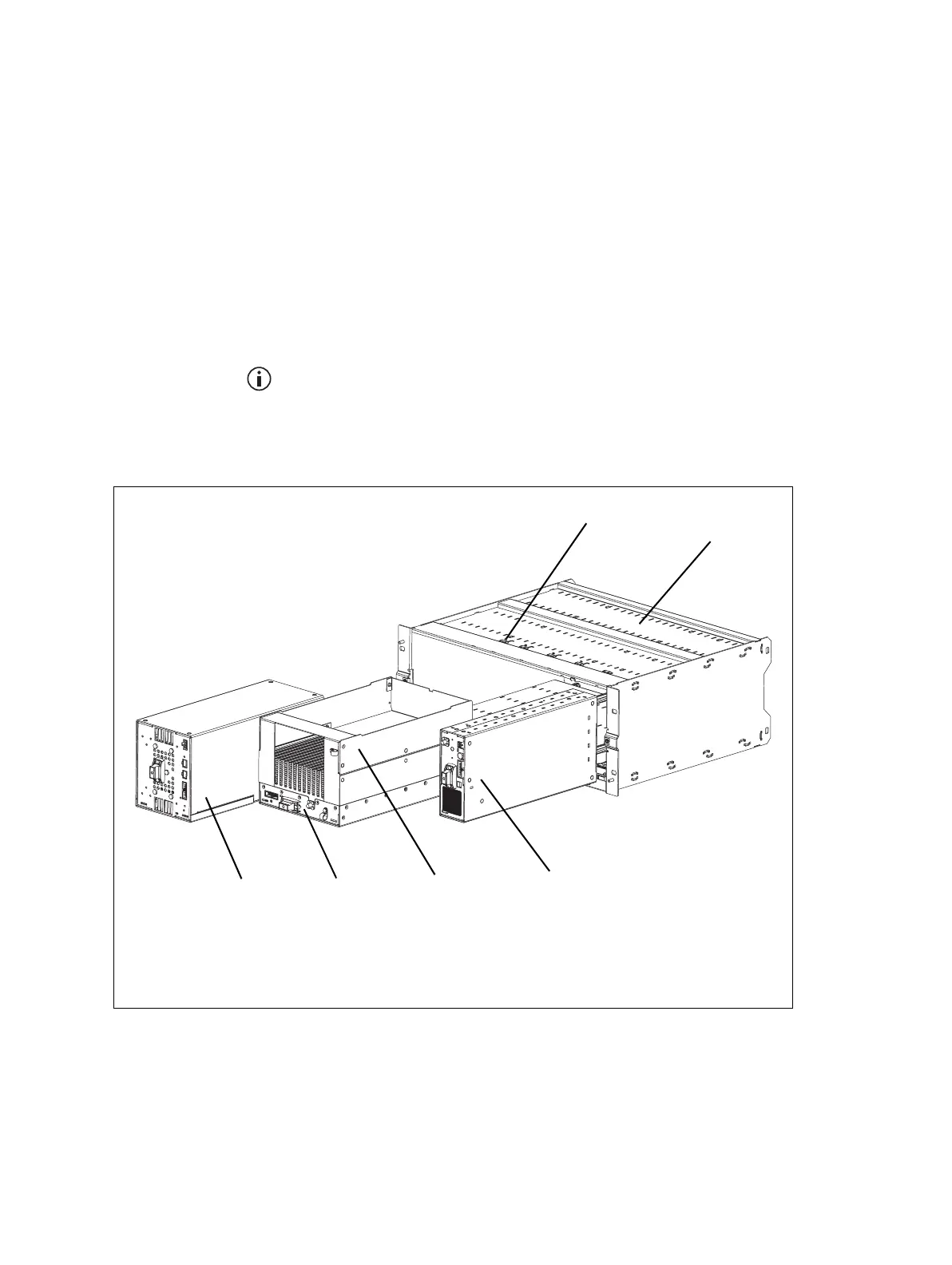
Figure 8.2 below shows the configuration for a typical 100 W base station.
Figure 8.2 Mechanical assembly - front of a 100W base station
b
PMU
e
reciter
c
PA
a
f
subrack
d
airflow duct
g
cable retaining clip
a. Not present in a gateway.
b
c
d
e
f
g
 Loading...


