54 Installation TB9100/P25 CG/P25 TAG Installation and Operation Manual
© Tait Limited March 2014
4. Adjust the receiver VCO trimmer until the actual band matches the
desired band. The bands turn green.
5. Click Finish. This stores the lock band in the reciter.
Setting the Exciter
VCO
1. Select the Frequency Setup tab, and double-click Set Exciter VCO.
The Set Exciter VCO Wizard appears.
2. Enter the center frequency (which must be a multiple of 500kHz) of
the lock band that you want to use, and click Next.
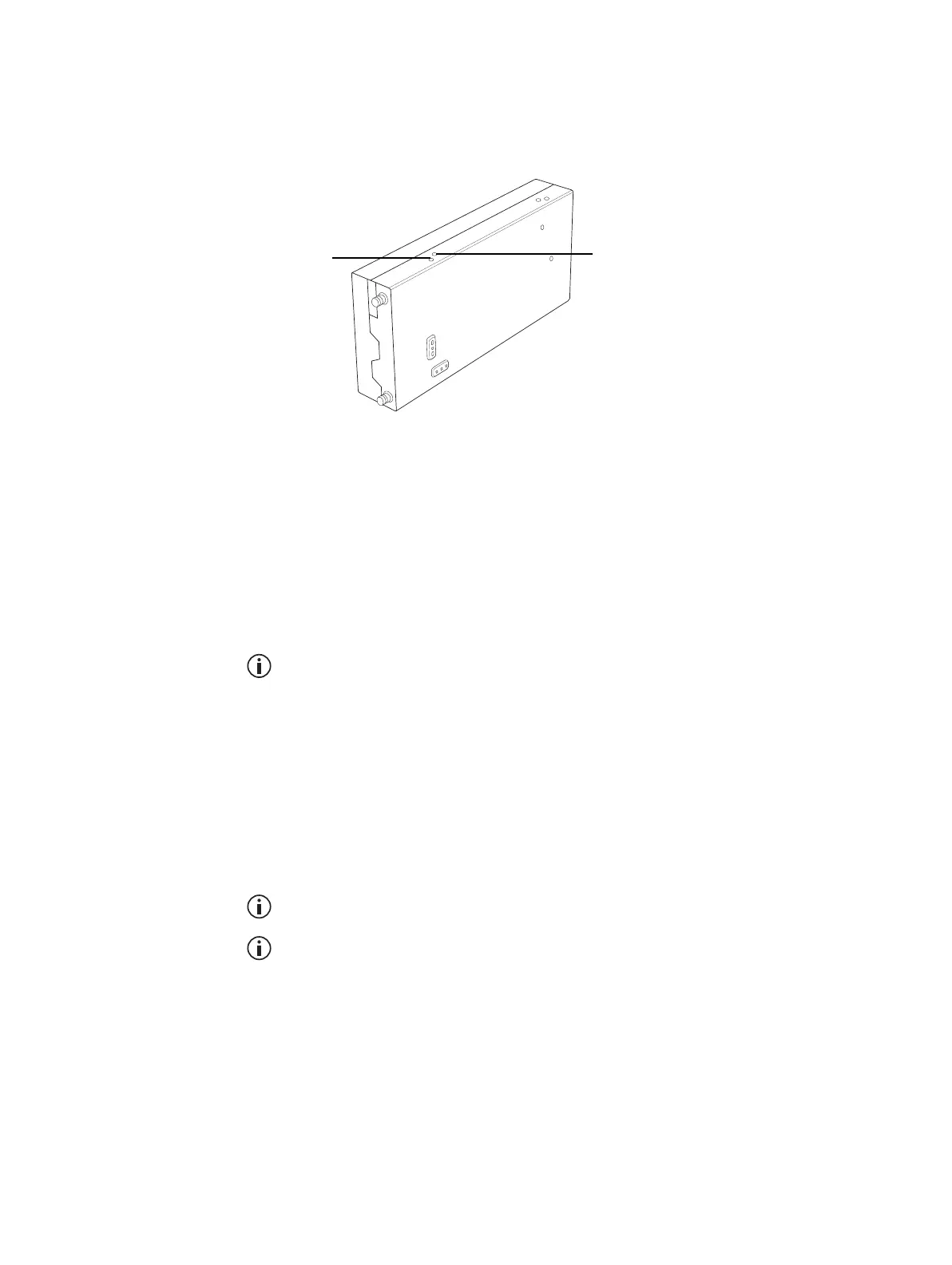
3. Insert the Murata tuning tool into the correct exciter VCO tuning
hole (see below) and adjust the trimmer until the actual band matches
the desired band. The bands turn green. Click Finish.
K-band and L-band exciters do not need their VCO to be set. They have
two VCOs and you simply choose which one to display on the CSS.
4. Disconnect the Calibration Software, to return the base station to
normal operation.
Tuning the Receiver
Front End
The following procedure is suitable if the base station will operate on a single
frequency. If it will operate on different frequencies across the switching
range, follow the instructions in the Calibration Software Help or manual
instead.
You do not need to tune the receiver front end in an L-band reciter.
You can tune the receiver front end by measuring either SINAD or
RSSI, and both these methods are described below. We suggest you tune
via RSSI first, and then use the SINAD method for subsequent repeti-
tions to refine the response.
1. Using a test set, feed a signal at the receive frequency into the reciter’s
RF input. The signal should have a level that gives around 12dB
SINAD (start at around -80dBm and adjust as needed).
Receiver VCO tuning hole for
H band (380 - 520 MHz) and
K band (792 - 824 MHz)
L band (852 - 930 MHz)
Receiver VCO tuning hole for
B band (136-174 MHz) and
C band (174 - 225 MHz)

 Loading...


