TB9100/P25 CG/P25 TAG Installation and Operation Manual Operation 81
© Tait Limited March 2014
Power LED
The green power LED is lit when the PMU is turned on and supplying
power to the subrack.
Carrier Button and
Transmit LED
The carrier button is a momentary press switch. When held down, it keys
the transmitter of the selected channel. The transmitted signal is
unmodulated, i.e. carrier only.
The red transmit LED is lit while the transmitter is transmitting.
Alarm LED The red alarm LED will flash at a rate of 2 to 5Hz when an alarm has been
generated by any of the base station modules. It will continue to flash until
the alarm is canceled, the fault is fixed, or the base station is in Standby
mode. Note that only those alarms which are enabled using the CSS will
cause this LED to flash.
The alarm LED also indicates when the base station is in Standby mode, as
described in the following table:
Microphone Button
and LED
The microphone button selects the speech mode for the microphone
transmission. The associated microphone LED indicates the type of speech
mode. Refer to “Microphone Operation” on page 82 for more
information.
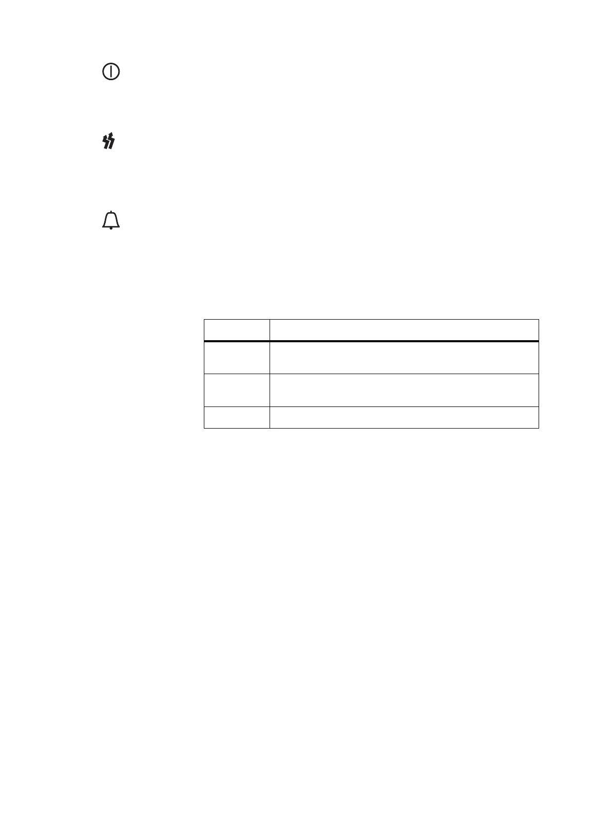
LED Description
On (steady) The base station is in Standby mode (regardless of the presence of
any fault).
Flash The base station is in Run mode, and one or more faults are
present.
Off The base station is in Run mode, and no faults are present.

 Loading...


