TM8100/TM8200 Service Manual Description 41
© Tait Electronics Limited June 2006
2.3.4 Internal Options Connector
When installing an internal options board, the internal options connector is
the electrical interface to the main board of the radio body.
The internal options connector provides similar I/O to the auxiliary
connector. The internal options connector is an 18-pin 0.1 inch pitch
Micro-MaTch connector.
Important The digital I/O signals are intended to interface directly
with compatible logic signals only. Do not connect these
signals to external devices without appropriate signal con-
ditioning and ESD protection.
2.3.5 Provision for External Options Connector
The radio has a mechanical interface for the external connector of an
internal options board. This external options connector can be a 9-way
standard-density or 15-way high-density D-range connector. If no internal
options board is installed (standard configuration), the hole for the external
options connector is sealed by a bung.
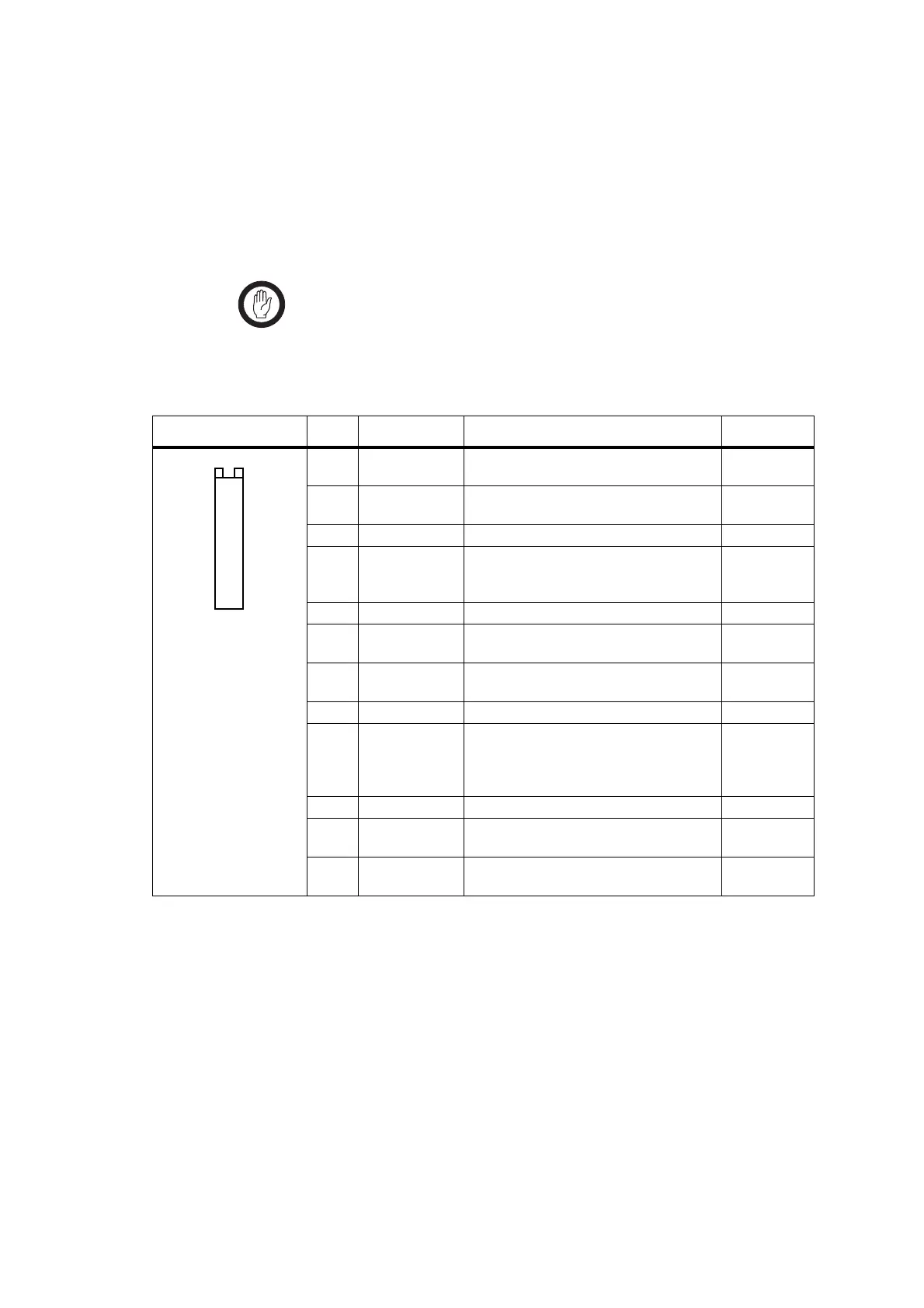
Table 2.4 Internal options connector – pins and signals
Pinout Pin Signal Description Signal type
1 13V8_SW
a
Switched 13V8 supply. Supply is switched
off when the Radio Body is switched off.
Power
2 AUD_TAP_OUT Programmable tap point out of the Rx or
Tx audio chain. DC-coupled.
Analog
3 AGND Analog ground. Ground
4 AUX_MIC_AUD Auxiliary microphone input.
Electret microphone biasing provided.
Dynamic microphones are not supported.
Analog
5 RX_BEEP_IN Receive sidetone input. AC-coupled. Analog
6 AUD_TAP_IN Programmable tap point into the Rx or Tx
audio chain. DC-coupled.
Analog
7 RX_AUD Receive audio output. Post volume
control. AC-coupled.
Analog
8 RSSI Analog RSSI output. Analog
9…15 IOP_GPIO1…7 General-purpose port for input and
output of data. Programmable function
and direction. With LK4 fitted, GPIO7 is a
power sense input
b
.
Digital.
3V3 CMOS
16 DGND Digital ground. Ground
17 IOP_RXD Asynchronous serial port - Receive data. Digital.
3V3 CMOS
18 IOP_TXD Asynchronous serial port - Transmit data. Digital.
3V3 CMOS
a. Can be switched or unswitched. For more information refer to “Connector Power Supply Options” on page 86.
b. For more information on hardware links refer to“Power-Sense Options” on page 83.
B
D
F
H
J
1!
1#
1%
1&
C
E
G
I
1)
1@
1$
1^
1*
top view
 Loading...


