TM8100/TM8200 Service Manual Description 43
© Tait Electronics Limited June 2006
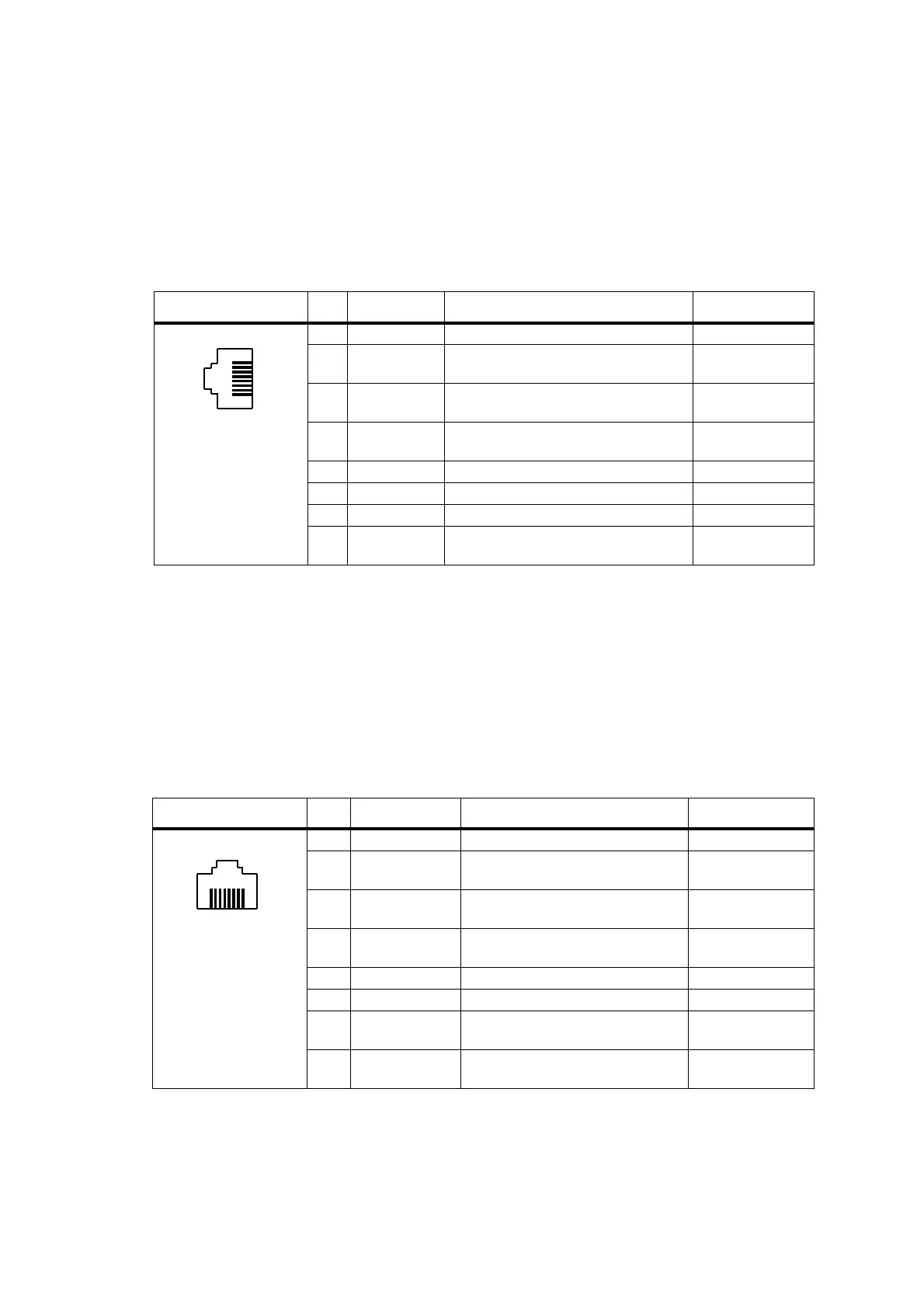
2.3.7 Microphone Connector
The microphone connector of the control head is an RJ45 socket.
When the control head is connected to the control-head connector of the
radio body using the loom provided, the microphone connector uses the
following eight control-head connector signals:
2.3.8 Programming Connector (RJ45 Control Head)
The programming connector of the RJ45 control head is an RJ45 socket.
When the RJ45 control head is connected to the radio body, the
programming connector uses the following signals.
Table 2.6 Microphone connector – pins and signals
Pinout Pin Signal name Description Signal type
1 MIC_RX_AUD Receive audio output. Analog
2+13V8
a
Power supply output. Switched off
when radio body is switched off.
Power
3 MIC_TXD Asynchronous serial port -
Transmit data.
3.3V CMOS
4 MIC_PTT PTT input from microphone. Also carries
hookswitch signal.
Digital
5 MIC_AUD Fist microphone audio input. Analog
6 AGND Analog ground. Analog ground
7 MIC_RXD Asynchronous serial port - Receive data. 3.3V CMOS
8 MIC_GPIO1 General purpose digital input/output. Open collector out
3.3V CMOS in
a. Can be switched or unswitched. For more information refer to “Connector Power Supply Options” on page 86.
B
I
front view
Table 2.7 Programming connector – pins and signals
Pinout Pin Signal name Description Signal type
1 PRG_RX_AUD Receive audio output. Analog
2 +13V8
a
Power supply output. Switched off
when radio body is switched off.
Power
3 PRG_TXD Asynchronous serial port -
Transmit data.
3.3V CMOS
4 PRG_PTT PTT input from microphone.
Also carries hookswitch signal.
Digital
5 PRG_MIC_AUD Fist microphone audio input. Analog
6 AGND Analog ground Ground
7 PRG_RXD Asynchronous serial port -
Receive data.
3.3V CMOS
8 PRG_ON_OFF Hardware power on/software-power
off input. Active low.
Digital
a. Can be switched or unswitched. For more information refer to “Connector Power Supply Options” on page 86.
B
I
front view

 Loading...


