TM8100/TM8200 Service Manual TMAA01-02 RS-232 Board 473
© Tait Electronics Limited June 2006
Important The external options connector screw-lock fasteners must
be tightened correctly before screwing the RS-232 board
onto the mounting posts
i
.
7. Screw the external options connector to the radio lid using the two
screw-lock fasteners
h
.
Tighten the fasteners
to a torque of 0.9N·m (8lbf·in).
8. Screw the RS-232 board to the mounting posts on the radio lid using
four M3x8 self-tapping screws
j
.
Tighten the M3x8 screws to a torque of 1.9N·m (17lbf·in)
Important For the RS232 board to be installed correctly in the radio’s
options cavity, the internal options connector loom
1)
must
be looped in the way shown in the diagram on page 473.
9. Plug the unattached end of internal options connector loom
1)
into
the internal options connector on the radio main PCB.
10. Refit the radio lid and top cover to the radio and screw the external
options cover seal
1!
over the external options connector, using the
two 4-40x3/16 screws
1@
.
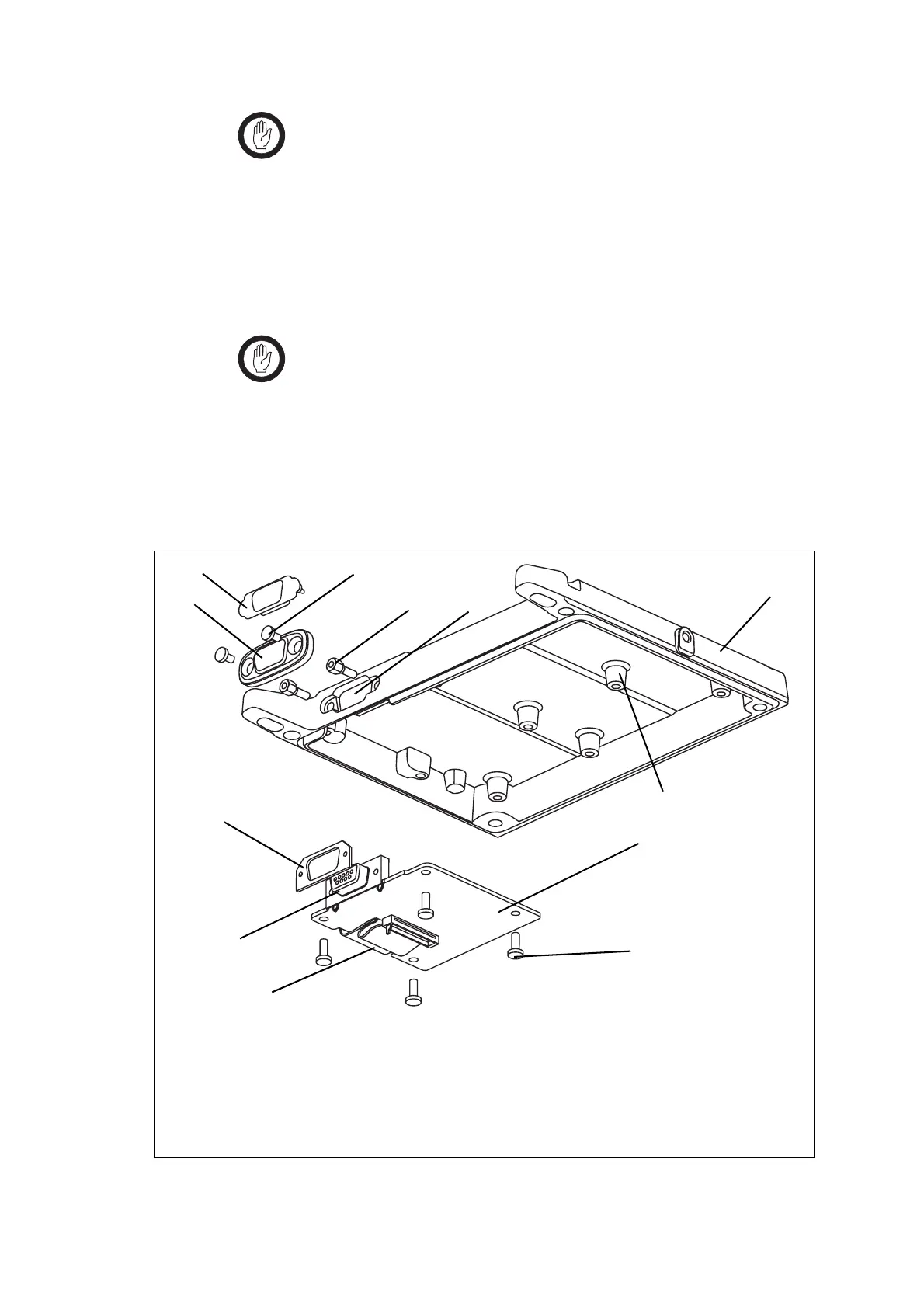
Figure 18.1 RS-232 board installation
b
radio lid
h
screw-lock fasteners
c
external options connector bung
i
mounting posts
d
foam seal
j
M3x8 self-tapping screws
e
external options connector cavity
1)
internal options loom
f
RS-232 board
1!
external options cover seal
g
external options connector
1@
4-40x3/16 screws
b
c
e
h
i
j
1@
1!
1)
d
f
g

 Loading...


