560 TMAA10-03 and TMAA10-06 High-Power Remote Speakers TM8100/TM8200 Service Manual
© Tait Electronics Limited June 2006
4. Run the free end of the speaker cable to the radio power cable and
install the two receptacles in the power connector, as described in the
“Power Connector Wiring” procedure.
Power Connector
Wiring
Insert the flying lead receptacles into the power connector socket, as shown
in the diagrams below.
Note The positive remote speaker wire has a white stripe.
1. TMAA10-03 remote speaker (25W radios)
For the TMAA10-03 remote speaker (25W radios), insert the flying
lead receptacles:
■ the positive wire and receptacle into the position nearest to the red
wire, and
■ the negative wire and receptacle into the position nearest to the
black wire.
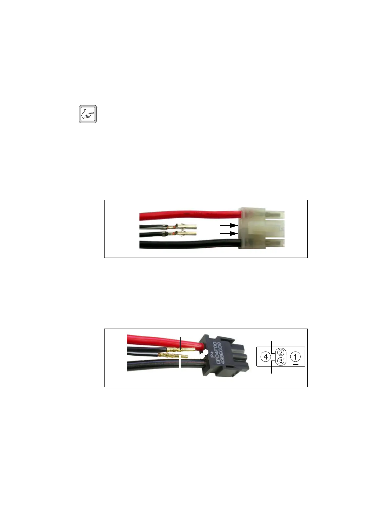
2. TMAA10-06 remote speaker (40W/50W radios)
For the TMAA10-06 remote speaker (40W/50W radios), insert the
flying lead receptacles:
■ the positive wire and receptacle into position 3, and
■ the negative wire and receptacle into position 2.
Connecting the
Remote Speaker
To connect the remote speaker, plug the flying lead into the housing socket.
To disconnect the speaker, release the locking mechanism and unplug the
flying lead.
power
connector
flying lead
connector
speaker +
speaker –
+13.8V
(red)
ground
(black)
power connector
flying lead
connector
speaker – (to pin 2)
speaker + (to pin 3)
+13.8V
(red)
ground
(black)
power connector
rear view
b
e
d
c
SPKR +
SPKR –
+

 Loading...


