TROUBLESHOOTING
OVERALL MACHINE
V-10TB53FR
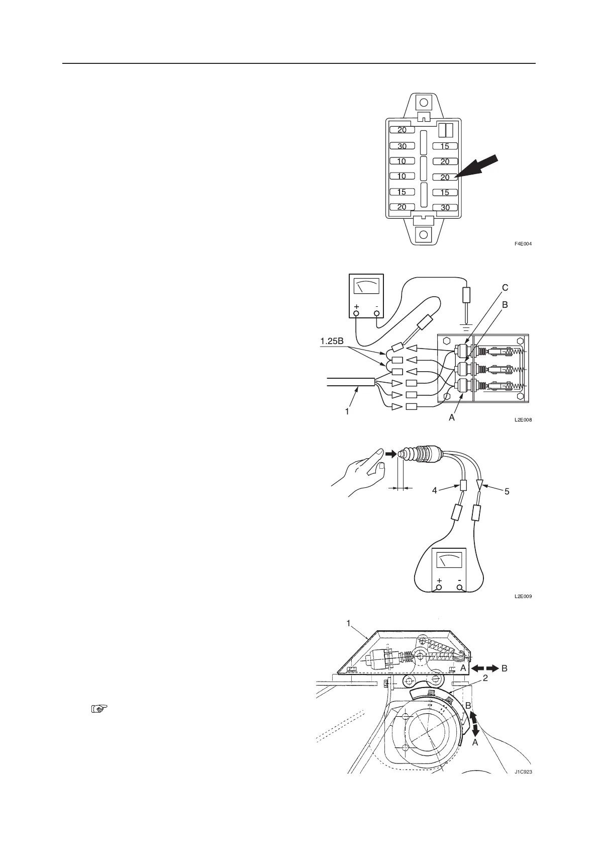
2. Inspect the fuse
Inspect the fuse of the power supply circuit that
operates the circuit of the interference prevention
system.
3. Inspect the interference prevention switch.
Turn the interference prevention switch “S. T. D
BUCKET” position.
While it is this condition, check if there is conti-
nuity with a tester.
4. Inspect the interference prevention system
<Boom switches A, B and C>
a. Inspect the wiring for inspecting the boom
switches.
Remove the wiring (1) from the boom switches
A, B and C.
Apply the test prod on the positive (+) side of
the tester to the terminal of the removed wiring
(wiring color is 1.25B) and ground the test
prod on the negative (-) side of the tester. Then,
turn the starter switch to the “ON” position and
check the voltage.
• If the voltage is 12 V, the wiring is in the
normal state. If not, inspect the wiring for
the fault location.
b. Inspect the boom switch.
Remove the boom switch, press the tip of the
boom switch with your finger, and apply the
tester in between the terminals (4) and (5).
• If the boom switch is turned on at a stroke of
2±1 mm assuring conductance, the switch is
in the normal state.
c. Confirm that the cam roller moves smoothly
along the cam plate (2) pushing the boom
switch.
Confirm that the offset switch is set in the state
with the stroke reduced by 4 mm from the free
state when the cam roller is on the cam plate
(2).
“III. Machine Configuration, Interfer-
ence Prevention System”
L2E009
5
4
."-"
L2E008
C
B
1
1.25B
A
J1C923
2
1
A
B
A
B
 Loading...