MACHINE CONFIGURATION
HYDRAULIC SYSTEM
III-37 TB53FR
DISASSEMBLY AND ASSEMBLY
Removing the Hydraulic Tank
1. Remove the cab.
“Removing the Cab”
2. Remove the covers around the tank.
“Removing the Covers”
3. Remove the counterweight.
“Removing the Upper Frame”
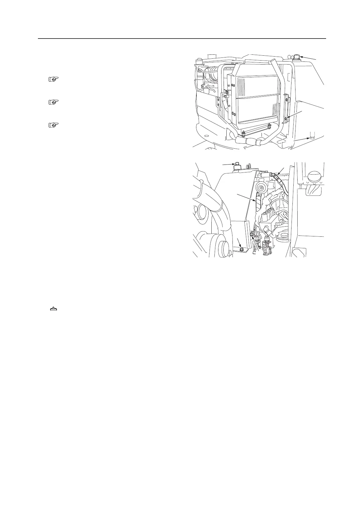
4. Remove the cap nut (1) on the air breather, and
push the button to release the pressure within the
tank.
5. Loosen the drain plug (2) and drain out the oil.
• Tank level capacity: 79 L
6. Disconnect the 3 low pressure hoses (4) from the
tank.
7. Disconnect the hydraulic hoses (5) from stop
valve.
8. Disconnect the 6 hydraulic hoses (6) from the
tank.
• Attach identification labels to individual hoses
for correct reassembling.
9. Remove the exhaust pipe fixing bolts (7).
10. Take out the fixing bolts (8), and suspend the tank
and remove it.
Tank: 57 kg
Installing the Hydraulic Tank
Follow the same procedure as for removal in the
reverse order.
J1C701
1
7
2
4
1
5
8
6
J1C702