MACHINE CONFIGURATION
INTERFERENCE PREVENTION SYSTEM
III-45 TB53FR
OPERATION
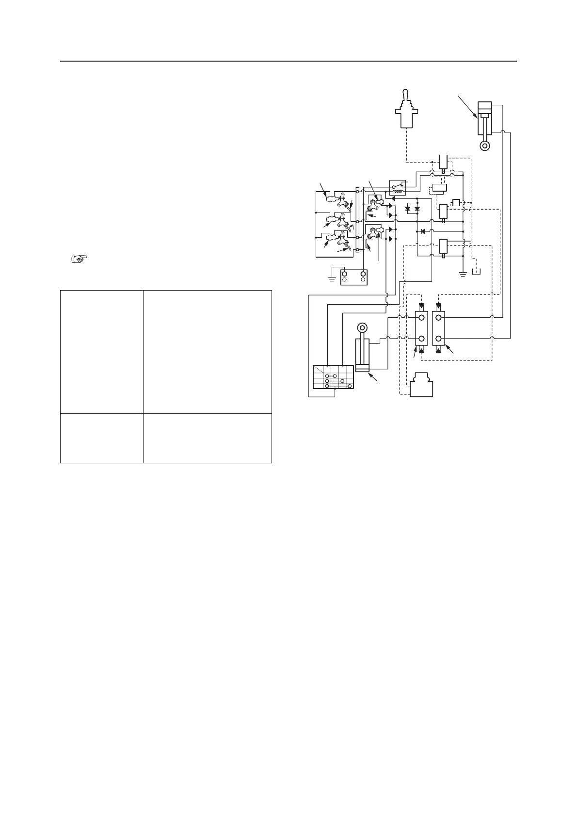
The interference prevention system detects the boom
position by the cams (1), (2), and (3), and the boom
switches A, B, and C; and detects the offset arm
position by the angle (4) and the offset switches R and
L. When the attachment enters the interference area,
the solenoids 1, 2, and 3 of the solenoid valve are
switched by the detected signal to control the spools
of the boom section (5) and the offset section (6) of the
control valve. Then, the boom cylinder (7) raise is
decelerated and stopped, and the left offset of the
offset cylinder (8) is stopped, thus preventing inter-
ference between the attachment and the cab.
• Structure and operations of the solenoid valve
“IV. Hydraulic Unit, Solenoid Valve”
• Switches and solenoids and their functions
Switches
Boom switch A
Boom switch B
Boom switch C
Offset switch R
Offset switch L
Decelerates boom raise.
Prevents interference between
boom and cab.
Prevents interference between
bucket and cab.
Prevents interference between
bucket and cab.
Prevents interference between
boom and cab.
Solenoids
Solenoid 1
Solenoid 2
Solenoid 3
Stops left offset.
Stops boom raise.
Decelerates boom raise.
J1C902
8
L
R
L
R
6
L
4
3
C
B
1
A
2
4
R
C
NO
SOL1
SOL2
SOL3
NC
7
+
-
5
BMH
L
1
2
3