EasyManua.ls Logo

tau D749MA - Control Panel Overview and Features; Introduction and Panel Features; Technical Characteristics; Terminal Board Connections

tau D749MA
14 pages
Print Icon
To Next Page IconTo Next Page
To Previous Page IconTo Previous Page
Loading...
17
D749MA
ENGLISH
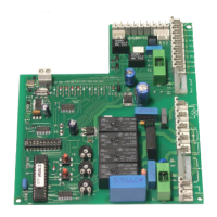
CONTROL PANEL FOR ONE-TWO 18V MOTORS WITH ENCODER
 
 
 
 
 
 
 
 
 
ATTENTION:
- do not use single cables (with one single wire), ex. telephone cables, in order to avoid
breakdowns of the line and false contacts;
- do not re-use old pre-existing cables;
- we recommend to use the TAU cable code M-03000010C0 to connect the motors to the
control board.
INTRODUCTION

 
 
and on after each command (mode where power is supplied by other energy
sources,
ex. batteries charged by a photovoltaic panel).


go off only when the controls to which they are associated are operated.
All the red LEDs must be off (each of them corresponds to a Normally Open input). The light
up only when the controls to which they are associated are operated.
TECHNICAL CHARACTERISTICS
Board power supply 
 
 
 
 
Motor power supply circuits voltage 
Auxiliary device circuits supply voltage 
Logic circuits supply voltages 
Operating temperature 
CONNECTIONS TO TERMINAL BOARD
Terminals Function Description
FS1 - FS2 POWER SUPPLY
-

power supply.
1 - 2 AUX INPUT

Note: if this input is used, jump J7 appropriately (see wir-
ing diagram).
ATTENTION: POWERING THE CONTROL UNIT WITH AN
EXTERNAL SOURCE, ALL THE OTHER 18V DC OUT-
PUTS BECOME THE SAME AS THE OUTSIDE VOLTAGE.

Related product manuals