19
D749MA
28 - 29 MOTOR (M1)
30 - 31 - 32 ENCODER (M1)
IMPORTANT:
Do not connect auxiliary relays or other devices tot he 18 V DC output (terminals 11 – 12)
to avoid malfunctions of the control unit. Use separated power supply / transformers
instead;
do not connect switching feeders or similar apparatus close to the automation that
may be a source of disturbance.
LOGIC ADJUSTMENTS
Note: when any adjusting devices (trimmers or dip-switches) on the control panel are oper-
ated, a complete manoeuvre must be carried out in order for the new settings to take effect.
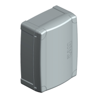
TRIMMER
T.R.A.
-
T.C.A.
FR.
Note: by rotating the TRIMMER FR. clockwise the sensitivity of the gear-
motor to obstacles diminishes and therefore the thrust force increases; vice-
versa, by rotating it counter-clockwise, the sensitivity of the gearmotor to
obstacles increases and therefore the thrust force diminishes.
Dip switch
1
AUTOMATIC
CLOSING
On
when completely open, closure is automatic after the set time on
Off
the closing manoeuvre requires a manual command.
2 2 / 4 STROKE
On
-
Off
in the same conditions, the same sequence of commands causes
(step-by step function) (see also dip switch 4)
.
3
CLOSES AGAIN
AFTER THE
PHOTOCELL
On
Off function off.
4 NO REVERSE
On the automation ignores the closure command during opening.
Off
5
PRE-
FLASHING
On
Off
6 FOTOTEST
On
Off
Note: to be used when the photocells are not used.
ENGLISH