6-4
OPERATING PROCEDURES
Models C709 & C717
Operating Procedures
6
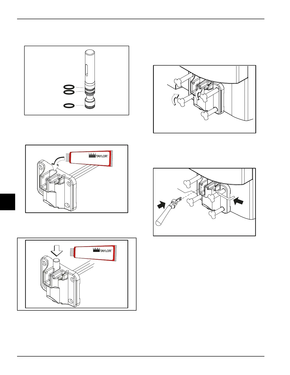
3. Slide the three O-rings into the grooves on the draw
valve and lubricate.
Figure 6-13
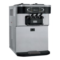
4. Lightly lubricate the inside of the top of the freezer
door valve cavity.
Figure 6-14
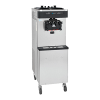
5. Insert the draw valve from the top, with the draw
handle slot facing forward.
Figure 6-15
6. Insert the baffle rod through the beater in the freezing
cylinder. With the door seated on the freezer studs,
install the handscrews with the longer ones on top.
Tighten equally in a crisscross pattern to make sure
the door is secured.
Figure 6-16
7. Position the draw handle with the adjustment screw
facing down. Slide the fork of the draw handle into
the slot of the draw valve. Secure with the pivot pin.
Figure 6-17
Note: The C709 features an adjustable draw handle
to provide portion control, giving a better, consistent
quality to your product and controlling costs.
The draw handle should be adjusted to provide a flow
rate of 5 oz. to 7-1/2 oz. (142 g to 213 g) of product
by weight per 10 seconds. To increase the flow rate,
turn the adjustment screw clockwise. Turn the
adjustment screw counterclockwise to decrease
the flow rate.
10390
Apply the appropriate
Taylor approved food safe lubricant.
HP
10500
Apply the appropriate
Taylor approved food safe lubricant.
HP