07/2015 13
TCS TürControlSysteme AG Subject to technical changes.
E-Mail: hotline@tcsag.de • www.tcsag.de PI_ISW3130-uk 2 A
General information on the conduit in TCS audio systems
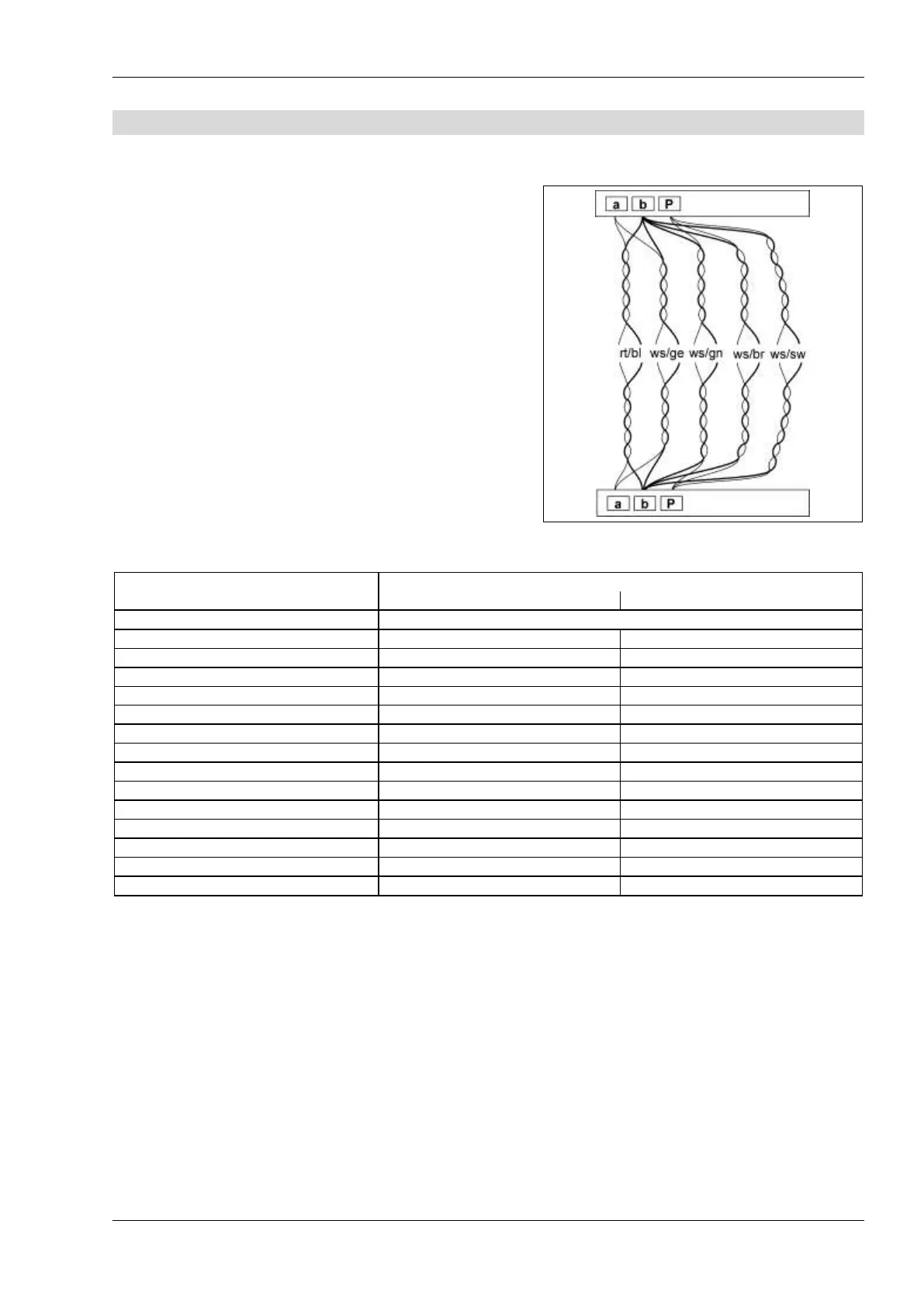
The conduit is determined by structural conditions and is only limited by ist length.
observe when selecting the cables: the loop re-
sistance can amount max. 20 Ω (see table)
in compliance to the max. permitted loop re-
sistance the cross section can be doubled,
which means, that for one wire two lines can be
used (illustration). The lines have to be twisted.
when using shielded cables: connect the shield-
ing with each other and put it one-sided on mass
(b-wire) in the power supply
optional strand- or star formed wiring
Table: loop resistance
principle loop resistance
measurement loop resistance
None of the devices (AS, IS or FE) should ever be
located more than 20 Ohm away from the power
supply and control unit (VS).
Switch off the 230 V / 50 Hz of the VS.
Install the a-b short-circuit at the VS.
Other devices do not disturb the measurement,
they can stay connected.
Measure the resistance on a/b IS at the strand of
the last indoor or front-door station.