1
・All specifications are subject to change without notice.
LS
Series
Input Voltage Range
Input voltage range is single phase 88 - 264VAC (47 - 63Hz) or
125 - 373VDC for LS25 to LS100.
For LS150, selectable switch 115/230VAC will decide the input
voltage range as mentioned in the table below.
Input voltage which is out of specification, may damage
the unit. For cases where conformance to various safety
specs(UL,CSA,EN) are required, input voltage range will be
100 - 240VAC (50/60Hz).
Note : LS series able to withstand Input Surge of 300VAC for 5 seconds.
LS150 – Selectable voltage range
Selected Range
Applicable Input
Voltage Range in VAC
Applicable Input
Voltage Range in VDC
115 88 - 132 NA
230 176 - 264 248 - 373
Output Voltage Range
V.ADJ trimmer is for output voltage adjustment within the range
of specifications. Turning the trimmer clockwise will increase
the output voltage. Note over voltage protection ( OVP) func-
tion may trigger if the output voltage is increased excessively.
Inrush Current
Power Thermistor is built in to protect the circuit from Inrush
Current.
Please select suitable input switch and fuse rating
in case of re-input the power at high temperature.
Over Voltage Protection (OVP)
The OVP function will shutdown the output except for LS25.
The input need to be removed for a few minutes, and then re-
input for recovery of the output. OVP setting is fixed and can-
not be adjusted externally.
Note : For LS25, OVP function will cause the output into ”hic-
cup” mode and damage the unit.
Over Current Protection (OCP)
OCP function operates when the output current exceeds OCP
specifications. The output will automatically recover when the
overload condition is removed. Do not operate overload or
dead short conditions for more than 30 seconds, which could
result in damage or insulation failure.
Output Ripple & Noise
Ripple & noise are measured at 20MHz by using a 300mm
twisted pair of load wires terminated with a 0.1uF film capaci-
tor & 47uF electrolytic capacitor. When load lines are longer,
ripple becomes larger. The output ripple cannot be measured
accurately if the probe ground lead of oscilloscope is too long.
At low temperature, large ripple & noise may also be observed
due to large ESR of the internal Electrolytic Capacitors espe-
cially at -25degC. Output voltage rise may not be smooth dur-
ing initial turn on at low temperature.
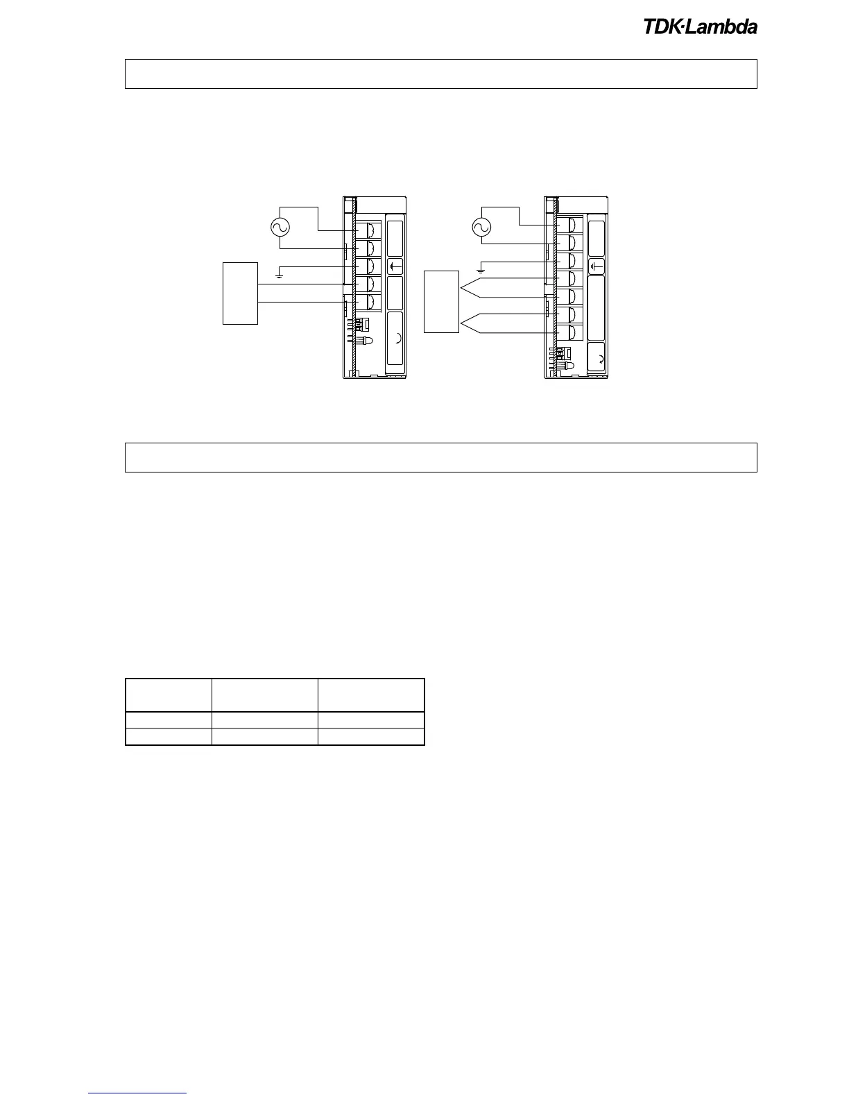
3. Explanation of Functions and Precautions
•
Input must be off when making connection.
•
Connect FG terminal to ground terminal of the equipment.
•
The output load line and input line shall be separated and twisted to improve noise immunity.
LS25, LS35, LS50, LS75 LS100, LS150
2. Terminal connecting method