114-94438 REV C1
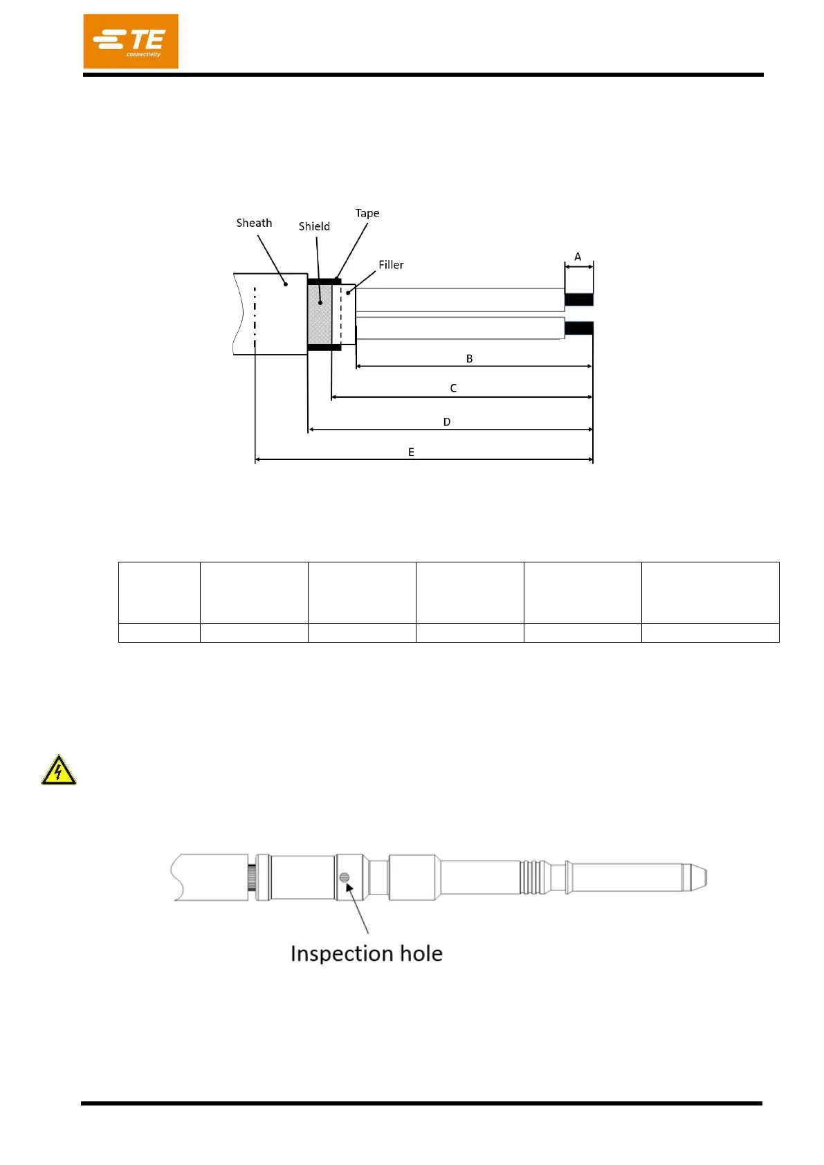
Alternative to prepar cable according step 2 figure 15, is it also possible to prepare cable similar
figure 16. In this case it is necessary to protect complete overlapping shield braid with tape (e.g.
Certoplast 9mm). A marking on outer isolation in a distance “E” (or in an offset to “E”) to the cut off
position is recommended to ensure the proper position of the outer isolation in the FAMILY SEAL AC
[POS.7].
Length to
shield braid
“C”
Length to outer
insulation
“D”
Position outer end
of COVER [POS.9]
“E”
Table 4
Crimp the conductors to the PIN DIA3.6 POWER AC [Pos. 3] with the specified tools. Care shall be
taken that all braids are caught in the crimp. Not inserted braids may jeopardize HV requirements! Wires
shall be completely inserted to be visible through the inspection hole (Figure 17). Crimp height H shall
be conform to dimension acc. table 1.
Any damage of the wire isolation must be avoided