114-94438 REV C1
Step 3
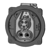
Preparation of PE single wire.
Dismantle PE-single wire cable acc. Figure 18.
THE SINGLE BRAIDS MAY NOT BE CUT OR DAMAGED DURING DISMANTLE PROCESS.
Variant of CABLE
EXIT [POS. 6]
Removal of
insulation "A"
Position outer end of
COVER [POS.9]
“B”
AC 90° (rect. right / left)
Table 5
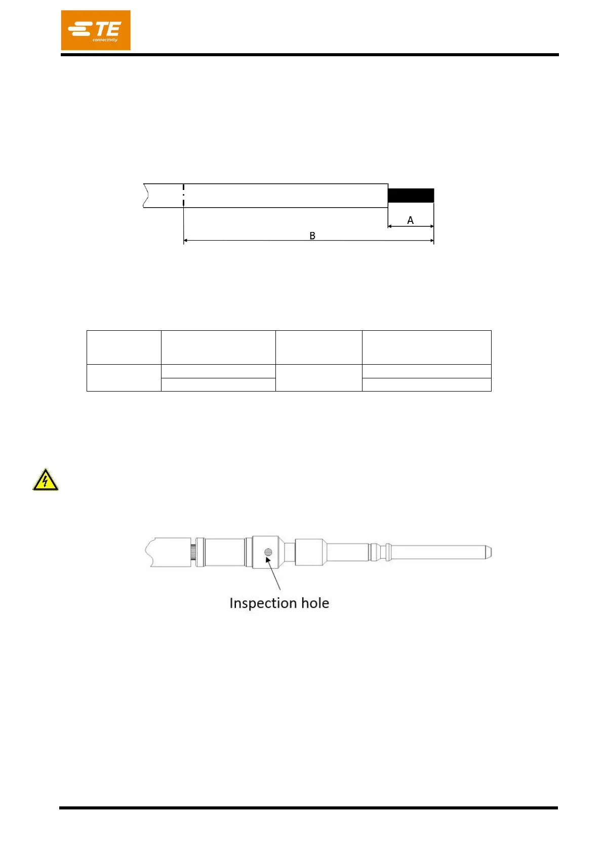
Crimp conductor on PIN DIA 2,8 POWER PE [Pos. 4] with the specified tools. Care shall be taken that
all braids are caught in the crimp. Not inserted braids may jeopardize HV requirements! Wires shall be
completely inserted to be visible through the inspection hole (Figure 19). Crimp height H shall be conform
to dimension
Any damage of the wire isolation must be avoided