114-94438 REV C1
Step 7
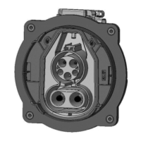
Assemble the Radial Seal [Pos. 5] to the Cable Exit Cover [Pos. 6]. Radial Seal should be properly seated
into the Collar of the Cable Exit Cover. Ensure also correct orientation of seal acc. figure 38.
Step 8
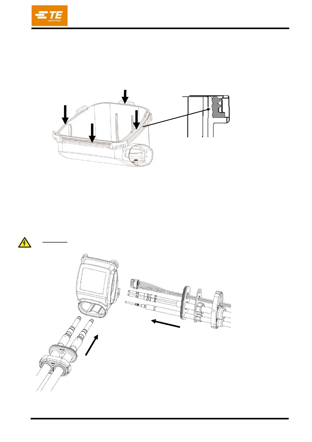
Pass the SIGNAL CONNECTOR, AC POWER PINS and PE PIN through the AC slot and DC pins
through DC slot in Combo Cable Exit [Pos. 6]
Attention: To mount the contact DC in contact cavity, you must wear firm gloves.