114-94438 REV C1
Step 9
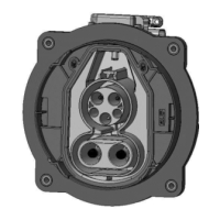
Insert the Contacts from the rear side into the Inlet Housing (figure 40) according to the cavity description
into their locking position.
ATTENTION: The correct contact positions must be ensured BEFORE pushing the contacts into
locking their cavities in locking position.
In case of wrong positioning of the contacts the complete assembly must be scrapped. There is no
rework allowed (risk of damaging contacts and/or locking geometry in housing)!
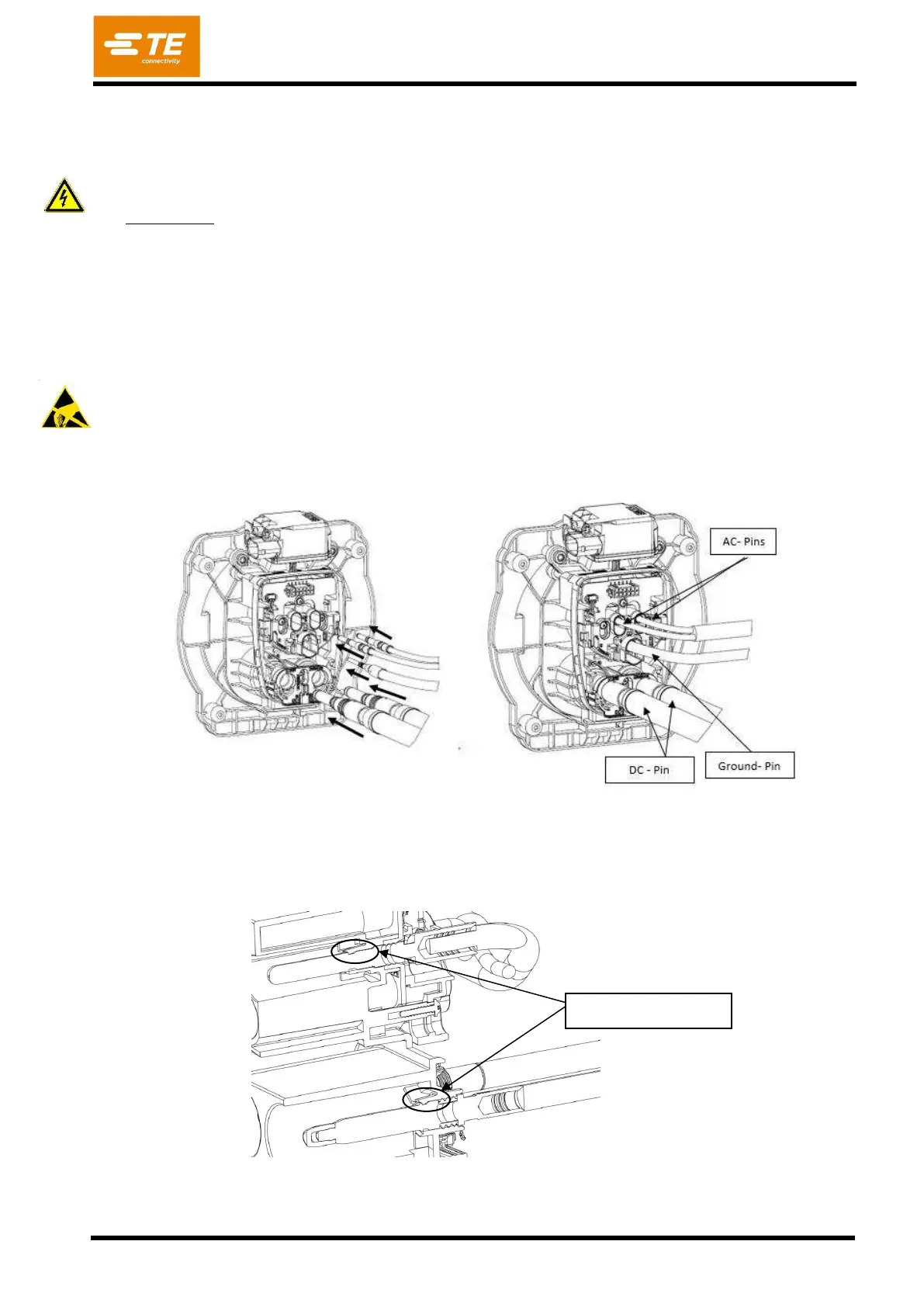
To ensure that the contacts are correctly inserted, pull and push with a low force on the cables (max.
10N) and check visually on the front side that the locking lances are properly engaged in the related pin
groove. The locking lances must not stay outside of the grooves (figure 41). Ensure the Seals are
properly positioned in their seats and are not damaged!
ESD safety required - The printed circuit boards are static sensitive devices, which can be damaged if
touched without the necessary electrostatic discharge (ESD) precautions. During handling of the open
inlet assembly ESD safety is required.