16 16
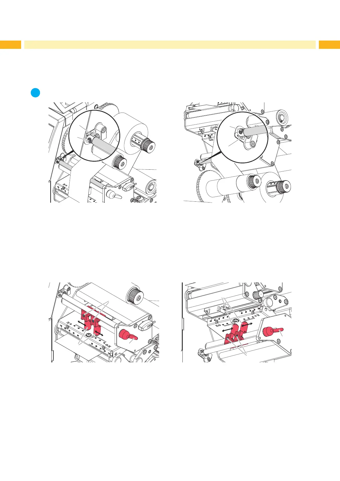
4.3 Setting the Feed Path of the Transfer Ribbon
Transfer ribbon wrinkling can lead to print image errors. Transfer ribbon deection can be adjusted so as to prevent
wrinkles.
i
Notice!
The adjustment is best carried out during printing.
1
2
2
1
Fig. 15 Setting the upper ribbon feed path Fig. 16 Setting the lower ribbon feed path
1. Read current setting on the scale (1) and record if necessary.
2. Turn screw (2) with Allen key and observe the behavior of the ribbon.
In the + direction, the inner edge of the ribbon is tightened, and the outer edge is tightened in the - direction.
4.4 Setting the Head Locking Systems
4.4.1 Setting the Plungers
2
4
1
1
2
3
Fig. 17 Setting the upper head locking system Fig. 18 Setting the lower head locking system
The printheads are pushed on via two plungers (1). In the basic setting the plungers are set in the middle of the
printhead retainer. This setting can be used for the most applications.
In the basic settings for Ladder format HS sleeves the 2 upper and lower printhead plungers should be positioned at
the 70 mm marks.
If the print density decreases in the outer areas when using very large media, the plungers can be displaced :
1. Turn lever (3) clockwise and the lever (4) counterclockwise to lock the printheads.
2. Loosen Allen screws (2) at the plungers (1) with Allen key.
3. Displace the plungers symmetrically to straddle the loaded media up to the maximum value of 70 on the scale.
4. Tighten the Allen screws (2).
4 Loading Media