TECDrive TEC-3 User Guide Revision 1.20
www.tecmotors.co.uk/tecdrive
4.6. Control Terminal Wiring
• All analog signal cables should be suitably shielded. Twisted pair cables are recommended.
• Power and Control Signal cables should be routed separately where possible, and must not be routed parallel to each other.
• Signal levels of different voltages e.g. 24 Volt DC and 110 Volt AC, should not be routed in the same cable.
• Maximum control terminal tightening torque is 0.5Nm.
• Control Cable entry conductor size: 0.05 – 2.5mm
2
/ 30 – 12 AWG.
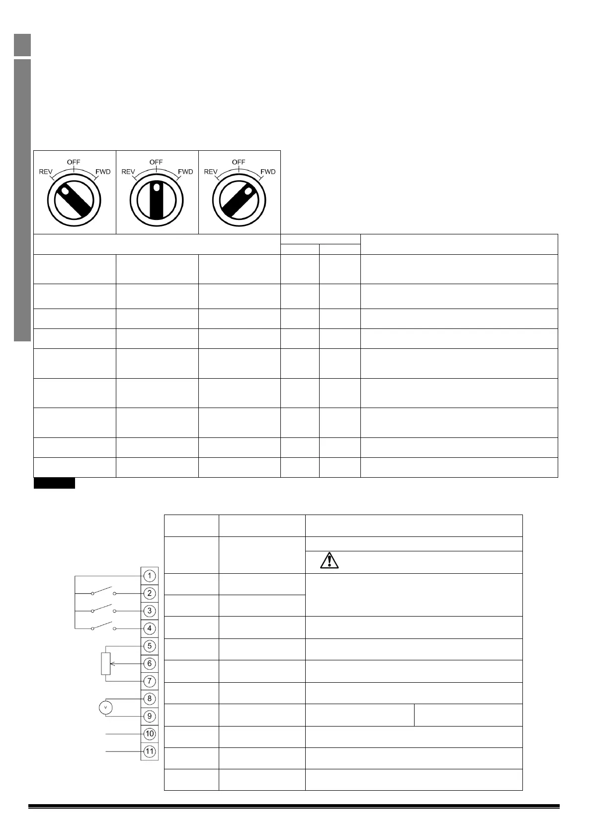
4.7. Using the REV/0/FWD Selector Switch (Switched Version Only)
By adjusting the parameter settings the TECDrive can be configured for multiple applications and not just for Forward or Reverse.
This could typically be for Hand/Off/Auto applications (also known and Local/Remote) for HVAC and pumping industries.
Factory Default Configuration
Run Forward or Reverse with speed controlled from the
Local POT
Run forward with speed controlled form the local POT
Run Reverse - disabled
Run Forward with speed controlled from the Local POT
Preset Speed 1 provides a ‘Jog’ Speed set in P-20
Run Forward or Reverse with speed controlled from the
Local POT
Run in Hand – Speed controlled from the Local POT
Run in Auto 0 Speed controlled using Analog input 2 e.g.
from PLC with 4-20mA signal.
In Speed Control the speed is controlled from the Local
POT
In PI Control, Local POT controls PI set point
Run in Preset Speed
Control
In Preset Speed Control, P-20 sets the Preset Speed
In PI Control, POT can control the PI set point
(P-44=1)
Hand – speed controlled from the Local POT
Auto – Speed Reference from Modbus
Hand – Speed reference from Preset Speed 1 (P-20)
Auto – Speed Reference from Modbus
To be able to adjust parameter P-15, extended menu access must be set in P-14 (default value is 101)
4.8. Control Terminal Connections
+24Vdc user output, 100mA.
Do not connect an external voltage source to
this terminal.
Positive logic
“Logic 1” input voltage range: 8V … 30V DC
“Logic 0” input voltage range: 0V … 4V DC
Digital Input 3 /
Analog Input 2
Digital: 8 to 30V
Analog: 0 to 10V, 0 to 20mA or 4 to 20mA
Analog Input 1 /
Digital Input 4
Analog: 0 to 10V, 0 to 20mA or 4 to 20mA
Digital: 8 to 30V
0 Volt Common, internally connected to terminal 9
Analog Output /
Digital Output
Analog: 0 to 10V,
Digital: 0 to 24V
0 Volt Common, internally connected to terminal 7
Contact 250Vac, 6A / 30Vdc, 5A