4. Unplug your phone connector from the wall socket and connect the splitter to the wall socket as show in
illustration 3.3.
5. Re-plug your phone to the filter, to the port called phone (on the right side in the picture).Your phone must be
always able to receive and make calls.
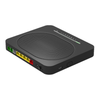
6. Connect the RJ11 (or RJ-45) cable to the last free socket of the filter (in the middle on the picture) and
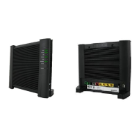
connect the other end of the RJ 11 (or RJ-45) cable to the modem on the grey DSL connector (see rear picture
of the modem).
7. Plug the RJ45 cable into your computer Ethernet port or into the WAN-port on the AT&T VPN Gateway or
Cisco Ethernet based routers for multi-users (see AT&T VPN Gateway user guide installation) and connect the
other end on the modem to one of the yellow connectors (see the rear modem picture).
8. Connect the power cable to the modem (see rear picture of the modem).
9. Plug the power supply to a power outlet and to the TG789VAC v2.
Now the physical modem installation is done.
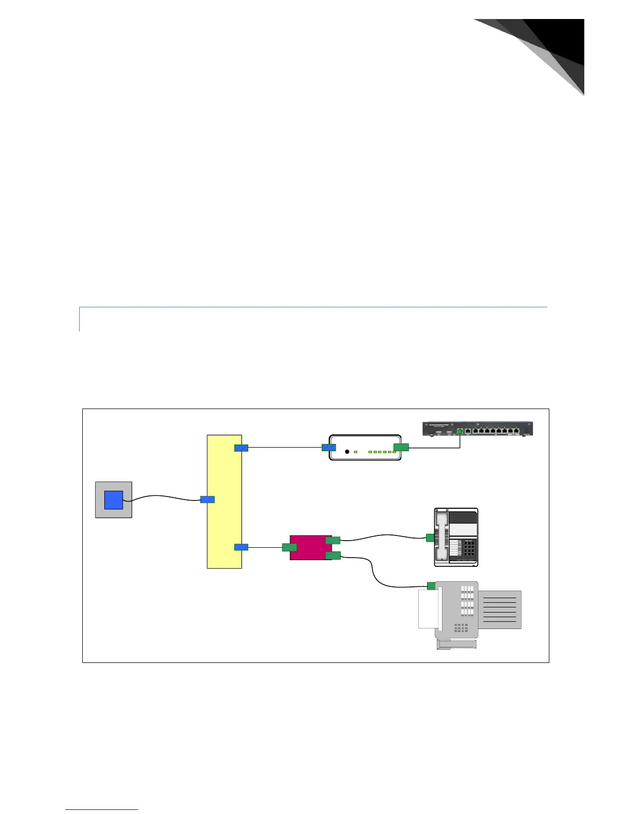
An ISDN installation normally has an NT1 unit installed, which is the demarcation (or end-point) of the
Telecommunication company’s responsibility of the ISDN line. An ISDN-splitter has to be installed directly connected to
the wall-socket or ISDN line, at the location where the phone line enters the home, before the line enters the NT1 unit,
as displayed in Illustration 3.4 on page 14. In some countries this is handled by the local Telephone company or
licensed installation companies, in others the customer is permitted to do this.
Figure 4 ADSLoverISDN using an ISDN splitter in the path from wall-socket to ISDN NT1.
The ISDN splitter ( Figure 4 ) is an un-powered active device, which draws its power from the ISDN line of the carrier.
 Loading...