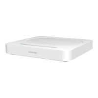
The remaining LEDs will not be used.
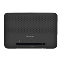
Illustration 2.2: LED overview
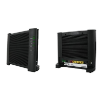
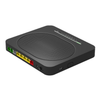
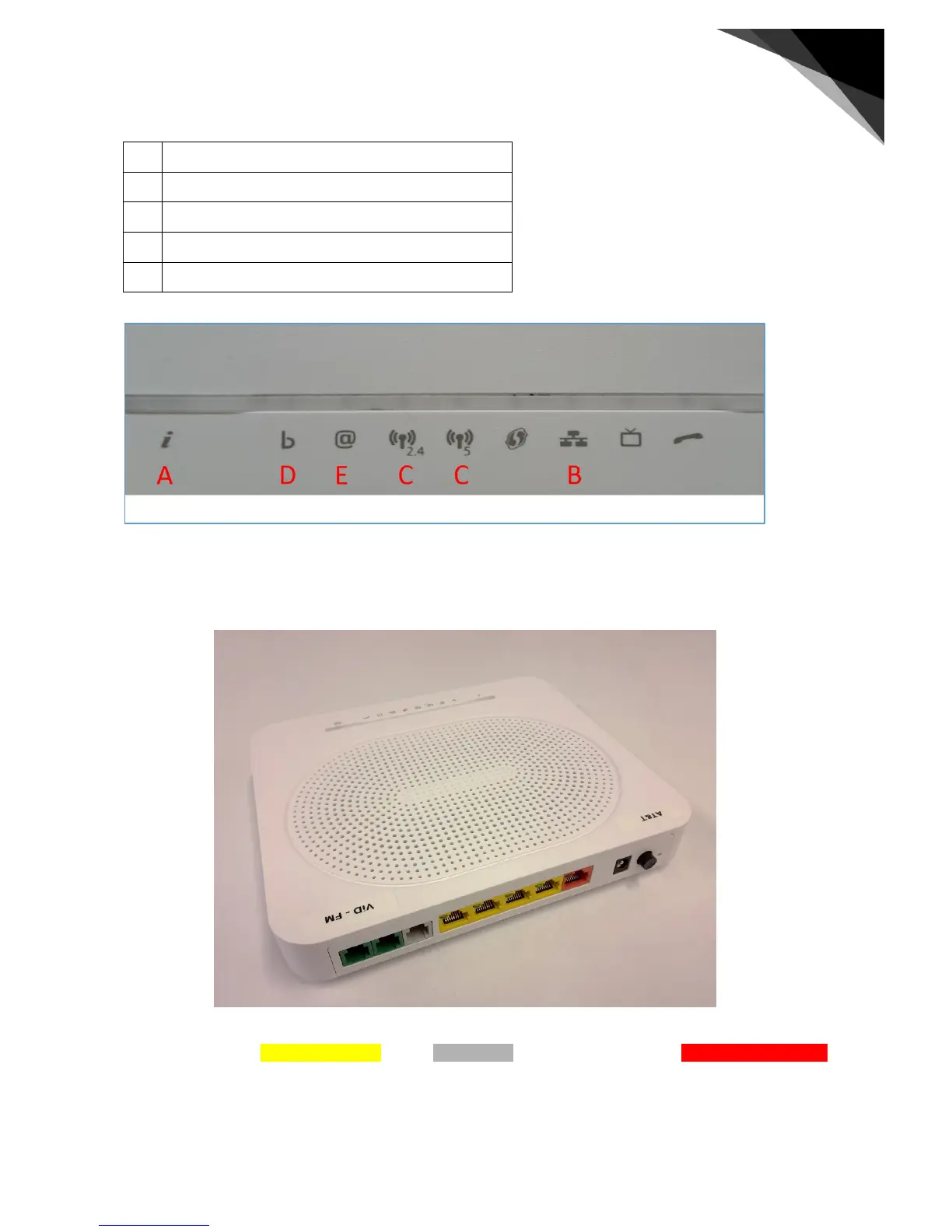
The ports to connect all cables to are at the backside of the modem. The layout of the ports is displayed in illustration
2.3.
Illustration 2.3: The port layout of the TG789VAC v2
The ports used are the yellow 4-port switch and the gray DSL-port. In some circumstances the red GigabitEthernet port
is used for FTTH support. This connection must then be made to an external fiber-optic modem.
The power socket is located next to the power switch on the right hand side on the modem.
 Loading...