When recordings are
made
at the same recording
level
and by
using different brands of
tape, even though the type
of
tape
(regular
or
"normal"
tape,
for
example)
is
used,
when
these
recordings are
played
back
the listener may notice
that the
high-frequency
sounds are
not
as distinct on one tape or the other,
etc.
The reason that such differences
may
be
noticed
is because there
are difterences
of the frequency response
(particularly
in the treble
range) between cassette
tapes
of the
various manufacturers
of
taoe.
Although,
for recordings
and
playback
in which
a noise-reduction
system
is used, it is the
principle
for such recordings that the
recording and
playback processes
be at the same recording level,
if, as a
result
of the
reason
described above, there is a difference of
the frequency response, there will result
a difference
in
the
processes
for recording and for
playback,
and correct
recordings
and
playback
cannot be accomplished.
In
order to
overcome this
problem,
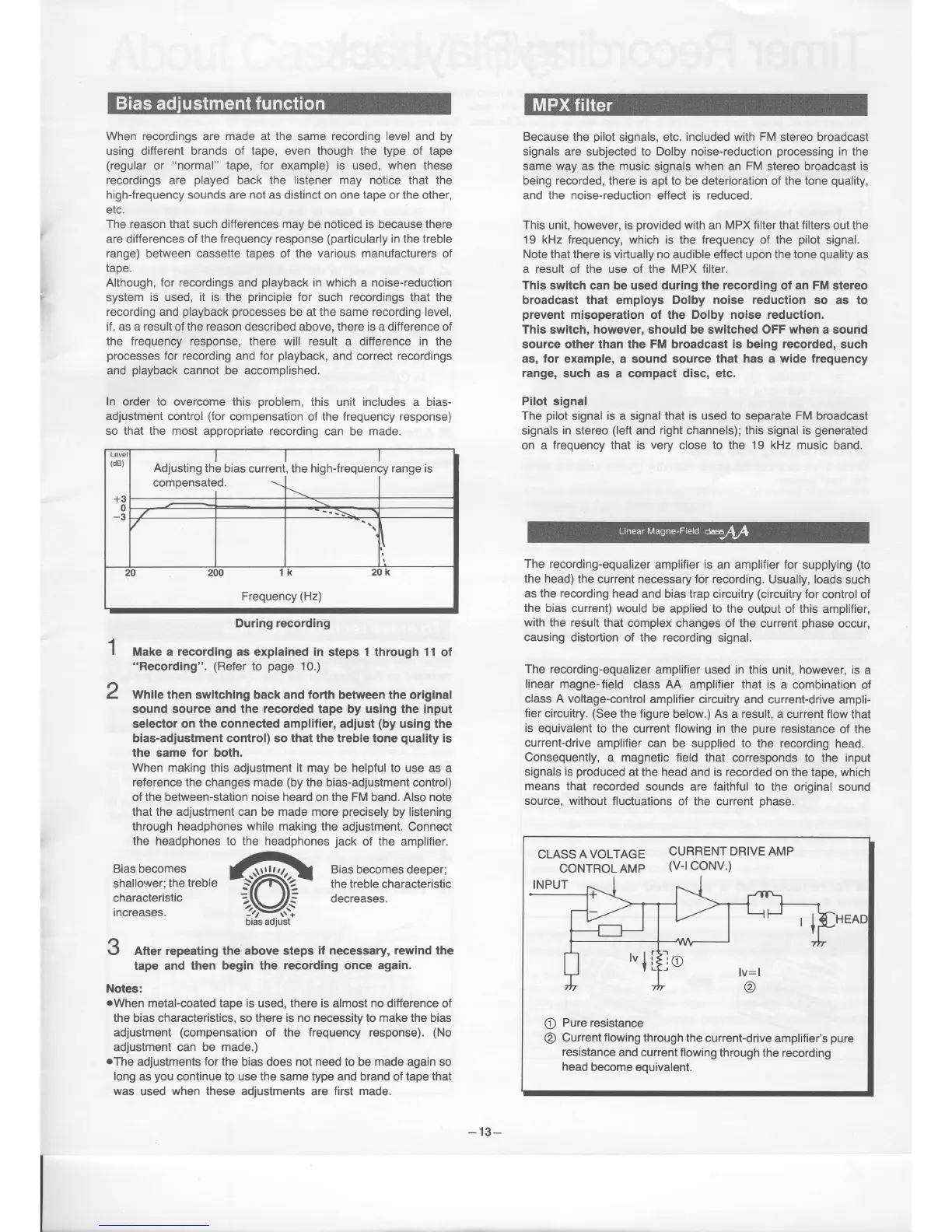
this unit includes
a bias-
adjustment control
(for
compensation
of the
frequency
response)
so that the most
appropriate recording
can be made.
During recording
I
I
Make a
recording
as explained
in
steps 1 through 11
ot
"Recording".
(Refer
to
page
10.)
Z
While
then swltching back and forth between the
original
sound source and the
recorded
tape by using the input
selectol on the connected amplifler, adjust
(by
using the
bias-adjustment control) so that the treble tone
quality
is
the
same
for both.
When making this adjustment it may
be
helpful
to use as a
reference
the changes
made
(by
the bias-adjustment control)
of
the
between-station
noise heard
on the
FM
band. Also note
that the adjustment can
be
made more
precisely
by
listening
through
headphones while
making the
adjustment. Connect
the headphones to the headphones
jack
of the amplifier.
..4
Bias.becom.es.
.. |r..}!!<',-l
Biasbecomesdeeper;
shal
lower; the treble
-
_YZ\\.2
-
the treble
characteristic
characteristic
7t\ )E
decreases.
increases.
?><i
bias adiust
O After repeating the above steps
if necessary, rewind the
tape and then
begin the recording once again.
Notes:
oWhen
metal-coated tape is
used, there
is
almost
no
difference of
the
bias characteristics, so
there is no necessity to make the bias
adjustment
(compensation
of the frequency response).
(No
adiustment
can
be made.)
.The
adjustments for the bias does not need to be made again so
long
as
you
continue to use the same type and brand of tape that
was
used
when these
adjustments are
first made.
Because
the
pilot
signals, etc.
included
with FM stereo broadcast
signals are
subjected
to Dolby noise-reduction
processing
in the
same way
as the
music
signals when an
FM
stereo broadcast is
being recorded, there is
apt to be deterioration of the
tone
quality,
and the noise-reduction effect is reduced.
This
unit,
however, is
provided
with
an
MPX filter that filters
out
the
19 kHz frequency, which is the frequency of the
pilot
signal.
Note that
there
is virtually no
audible effect
upon
the
tone
quality
as
a result
of
the use
of the
MPX filter.
This
switch can be used during
the recordlng
of an
FM
stereo
broadcast
that employs
Dolby noise reduction
so as
to
prevent
misoperation
of
the Dolby noase reduction.
This switch, however,
should
be switched OFF when a
sound
source other than the FM broadcast
is
being
recorded,
such
as, for
example, a sound source
that has a wide frequency
range,
such as a compact disc, etc.
Pllot
signal
The
pilot
signal
is
a signal
that is used to
separate
FM
broadcast
signals
in
stereo
(left
and right channels); this signal is
generated
on
a frequency that is very close lo the 19 kHz music
band.
The
recording-equalizer
amplifier is an
amplifier
for
supplying
(to
the head)
the
current necessary for recording.
Usually, loads such
as
the recording
head
and bias trap circuitry
(circuitry
for
control of
the
bias current) would
be applied to the output of this
amplifier,
with the result
that
complex changes of the
current
phase
occur,
causing
distortion of the recording
signal.
The
recording-equalizer
amplifier used in this
unit, however, is
a
linear magne-field
class M amplifier that is
a combination
of
class A voltage-control
amplifier
circuitry and current-drive
ampli-
fier
circuitry.
(See
the figure
below.) As a result,
a current flow that
is
equivalent to the
current
flowing
in the
pure
resistance
of the
current-drive
amplifier can
be supplied
to
the
recording
head.
Consequently,
a magnetic field that
corresponds to the input
signals
is
produced
at the head
and
is recorded
on the tape, which
means
that recorded
sounds are faithful to the
original sound
source, without
fluctuations
of the current
phase.
L
(dB)
+3
0
-3
I
Adjusting
the bias
currenl
compensated.
\\
,
the
high{requen
:y
range rs
..>\
20
200
1 l( 20K
Frequency
(Hz)
CLASS
A VOLTAGE
CURRENT DRIVE AMP
CONTROLAMp
U-lCONV.)
Pure resistance
Current flowing
through the
current-drive
amplifier's
pure
resistance
and
current flowing through
the recording
head
become
equivalenl.
-
13-