http://servis-manual.com/
13.3 Head azimuth adjustment (Deck 1/2)
TOP PREVIOUS NEXT
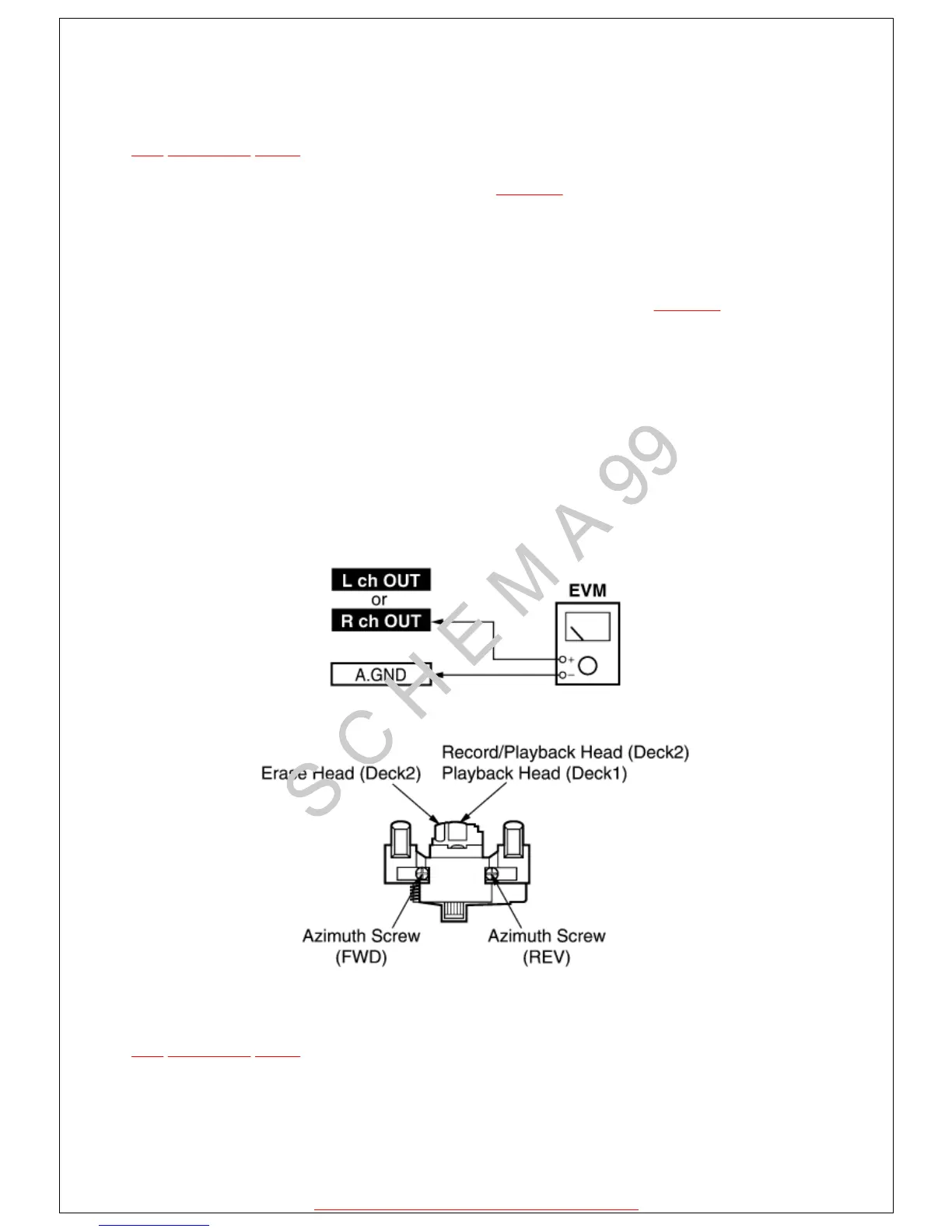
1.Connect the measuring instrument as shown in Fig. 13-1.
2.Replace azimuth screws for both forward and reverse directions after removing the screw-
locking bond left on the head base. (Supply part No. of azimuth screw: RHD17015 )
3.Playback the azimuth adjustment portion (8 kHz, -20 dB) of test tape (QZZCFM). Adjust the
azimuth screw until the outputs of the L/R ch are maximized. Refer to Fig. 13-2. Make sure
that thedifference in the peak level between the left and right channels does not exceed 0.5 dB.
4.Perform the same adjustment in reverse playback mode.
Check of the level difference forward and reverse directions.
5.Playback the playback gain adjustment portion (315 Hz, 0 dB) of test tape (QZZCFM). Check
if level difference between forward and reverse direction is within 1.5 dB.
6.After the adjustment, apply screw lock to the azimuth screw.
Fig. 13-1.
Fig. 13-2.
@
TOP PREVIOUS NEXT
20. 10. 2004file://C:\Documents%20and%20Settings\Admin\Plocha\SCHÉMATA\VIDEA\PAN...