7
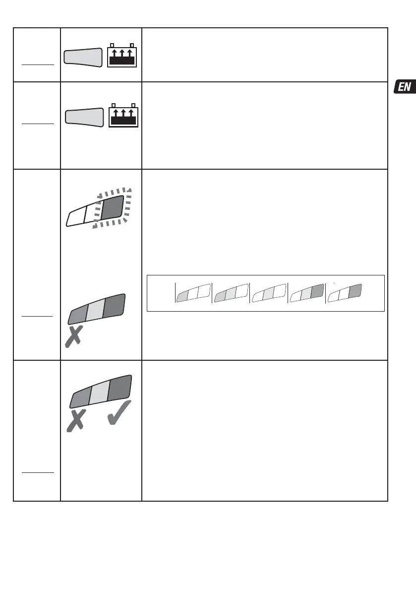
STEP 5
CHARGE
Standard:
STEP 6
LED #4 : YELLOW
Engages if the battery state of charge was 50% or higher (as tested in
STEP 3) or once the battery has been sufficiently recovered during STEP 4
(5). A constant current of 1A up to a voltage of 14.2 -14.4V is delivered to the battery.
NOTE CAN-bus: The program automatically resets 2 minutes after manual
disconnection, OR if the vehicle CAN-bus system has de-activated the controlled 12V
outlet and the program could not re-activate the outlet within 2 minutes.
STEP 6
OPTIMIZE
Standard:
STEP 7
LED #4 : YELLOW
Engages when the voltage has reached 14.3V for the first time during
CHARGE mode.
Pulsed absorption: Current is delivered in pulses, varying between 0.2 and 1A and up to
a voltage of 14.2 - 14.4V, to bring the battery to full charge in the shortest possible
time. Verification: Once the current demand is less than 0.2A the charging voltage is
now limited at 13.6V whilst the battery's charge level is verified.
If the battery requires further charging the program will revert to pulsed absorption.
NOTE: Charge time is usually extended if there is higher than expected current draw by
connected circuitry or battery health is less than optimal.
For safety reasons there is an overall charge time limit of 48 hours.
STEP 7
TEST after
charge
Standard:
STEP 8
LED #5 FLASHING
TEST after charge : Delivery of current to the battery is interrupted for
30 minutes** to allow the program to determine the battery’s ability to
retain charge.
This will prompt the CAN-bus system to disable the 12V outlet within it's own set time
limit, disconnecting the battery from the charger. At the conclusion of the test period
the program will once again initialize the CAN-bus controlled 12V outlet to measure the
battery's voltage and then proceed to MAINTENANCE CHARGE during which the result
of the test is displayed.
Consult the table below (or on page 2) to match TEST LED indication to an estimated
state of charge percentage (SOC%). A significant problem exists if the battery is unable
to retain sufficient charge during this voltage retention test.
More information is provided in the section “NOTES ON TEST RESULTS”.
7
6
5
80 100%604020AGM
100% 806040STD
7
6
6
5
0
0
** STANDARD PROGRAM ONLY: IF the result in STEP 3 was RED (LED #7) or RED &
YELLOW (LED #6 & 7), indicating a deep discharged battery, the voltage retention test is
extended to 12 hours to confirm battery health. The TEST result (indicated on LED # 5,
6, 7) is adjusted in real time according to the measured battery voltage. The TEST will
be interrupted if LED #7 (red) lights.
STEP 8
OptiMATE
'365'
MAINTAIN
Standard:
STEP 9
LED #5 / 6 / 7 ON
For batteries with a good
state of health LED #5
(green) will remain on.
Exception: STD wet cell
batteries with filler caps
have a lower fully charged
voltage: LED #5 remains
on together with LED #6.
MAINTENANCE CHARGE: LED #5 / 6 / 7 steady on
according to state of charge measured during STEP 7 (8).
Float voltage setting: 13.6V
STD maintenance mode consists of 30 minute float charge periods followed by and
alternating with 30 minute ‘rest’ periods, during which there is no charge delivered.
This “50% duty cycle” prevents loss of electrolyte in sealed batteries and minimizes
gradual loss of water from the electrolyte in batteries with filler caps, and thereby
contributes significantly to optimizing the service life of irregularly or seasonally used
batteries.
During “float charge” a continuous LOW CURRENT PULSE IS DELIVERED TO PREVENT
SULFATION, further extending battery power and life.
NOTE CAN-bus: The program automatically resets 2 minutes after manual
disconnection, OR if the vehicle CAN-bus system has de-activated the controlled 12V
outlet and the program could not re-activate the outlet within 2 minutes.
CHARGE CURRENT BAR: LEDs #8 - Lights when pulsed or continuous current is delivered to the battery.
DUAL PROGRAM : TO CHANGE FROM ONE PROGRAM TO ANOTHER:
1.
Disconnect the charger from AC supply.
2. Attach the battery clip set to the charger and connect the negative clip directly to the positive clip.
3. Re-connect the charger to AC supply.
4
TEST
30m - 12h
5
4
5
6
7
7