8 TS1061 Dual Wiegand Interface Installation Manual
Connections
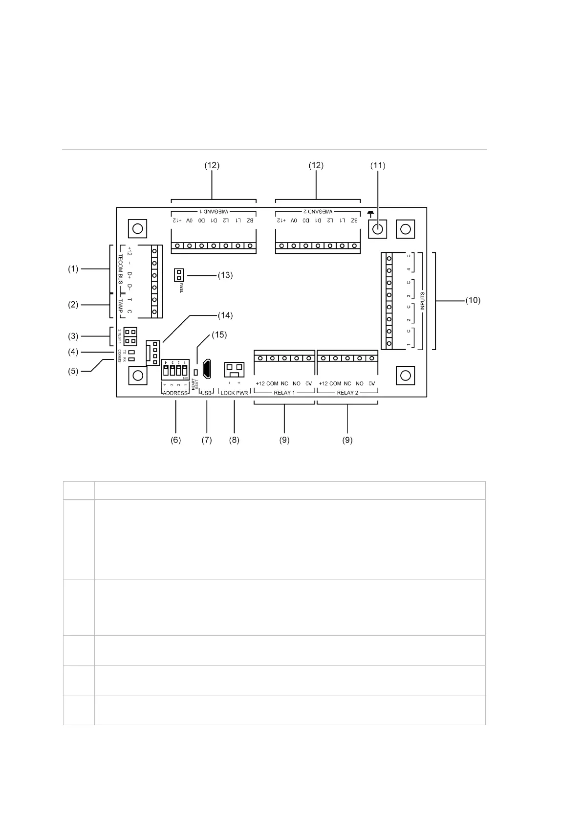
See Figure 2 below for the locations of connectors and other items. See
“Appendix D: Cabling requirements” on page 23 for recommendations for the
application and wiring of Challenger equipment.
Figure 2: TS1061 board details
Figure 2 legend
ChallengerPlus application: Connect the TECOM BUS +12, TECOM BUS −, TECOM
BUS D+ and TECOM BUS D− terminals to the ChallengerPlus panel’s COMMS 1 or
COMMS 2 cable.
Network Access Controller application: Connect the TECOM BUS +12, TECOM BUS
−, TECOM BUS D+ and TECOM BUS D− terminals to the Network Access Controller’s
BUS 1 or BUS 2 cable. (Only use if (14) is not used).
Connect the TAMP T and TAMP C terminals to the panel tamper switch in the enclosure.
Short circuit for sealed, open circuit for unsealed. Must be sealed if not used. Can only be
used with normally closed contacts such as the panel tamper switches.
Note: Panel tamper switch must only be connected to one board in the enclosure.
TEST 1 and TEST 2 links. Both links are used when updating firmware via CTPlus (refer
to “Upgrading firmware” in the CTPlus online help for instructions).
COMMS Tx LED to indicate activity on the RS-485 LAN/bus. See “LED indications” on
page 19.
COMMS Rx LED to indicate activity on the RS-485 LAN/bus. See “LED indications” on
page 19.