EasyManua.ls Logo

TECOM TS1061 - DIP Switch Settings; Interface Addressing Ranges; ChallengerPlus Panel Settings

TECOM TS1061
27 pages
Print Icon
To Next Page IconTo Next Page
To Previous Page IconTo Previous Page
Loading...
TS1061 Dual Wiegand Interface Installation Manual 5
DIP switch settings
The TS1061 Dual Wiegand Interface can be connected to a ChallengerPlus
panel’s COMMS 1 or COMMS 2, or a Network Access Controller’s BUS 1 or
BUS 2. The Interface is polled as a DGP. The addressing ranges that can be
used depend on whether the Interface is connected to a ChallengerPlus or a
Network Access Controller, as shown in Table 2 below.
Table 2: Interface addressing ranges
LAN/Bus
Address
Polled as
ChallengerPlus
COMMS 1
1 to 12
DGP 1 to 12
COMMS 2
1 to 12
DGP 17 to 28
Network Access Controller
BUS 1
1 to 15
DGP 1 to 15
BUS 2
1 to 16
DGP 17 to 32
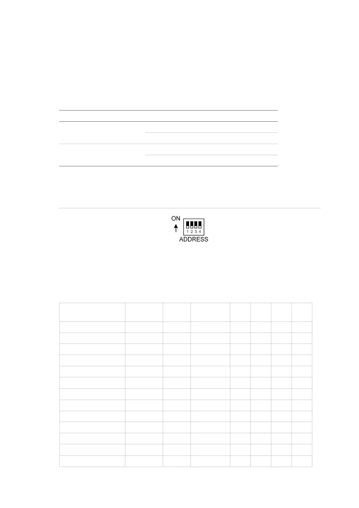
Use the four-segment Address DIP switch to set the address.
Figure 1: Address DIP switch
Settings for connection to ChallengerPlus panel:
The DIP switch settings for connection to a ChallengerPlus panel are shown in
Table 3 below.
Table 3: DIP switch settings for connection to ChallengerPlus
ChallengerPlus LAN
Address
Polled
as
Door
numbers
S1-1
S1-2
S1-3
S1-4
COMMS 1
1
DGP 1
17, 18
I
O
O
O
COMMS 1
2
DGP 2
21, 22
O
I
O
O
COMMS 1
3
DGP 3
25, 26
I
I
O
O
COMMS 1
4
DGP 4
29, 30
O
O
I
O
COMMS 1
5
DGP 5
33, 34
I
O
I
O
COMMS 1
6
DGP 6
37, 38
O
I
I
O
COMMS 1
7
DGP 7
41, 42
I
I
I
O
COMMS 1
8
DGP 8
45, 46
O
O
O
I
COMMS 1
9
DGP 9
49, 50
I
O
O
I
COMMS 1
10
DGP 10
53, 54
O
I
O
I
COMMS 1
11
DGP 11
57, 58
I
I
O
I
COMMS 1
12
DGP 12
61, 62
O
O
I
I
COMMS 2
1
DGP 17
81, 82
I
O
O
O