12 TS1061 Dual Wiegand Interface Installation Manual
Door lock relay wiring
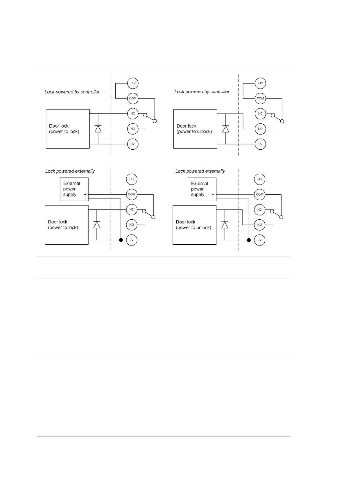
Figure 4 below details the wiring for the relay terminal blocks.
Figure 4: Door lock wiring options (relay shown de-energised)
Note: A suppression diode such as 1N4004 must be used in door lock circuits.
The diode must be co-located with the lock.
Inputs
Each pair of input terminals may be connected to a device such as a detector or
reed switch.
The ChallengerPlus panel or Network Access Controller can monitor its input
circuits for four states (sealed, unsealed, open circuit, and short circuit). This is
accomplished by using two end-of-line (EOL) resistors in each input circuit, as
shown in Figure 5 on page 13.
Note: ChallengerPlus panels and Network Access Controllers can have various
EOL resistor values for input tamper monitoring (the default is 10 kΩ resistors).
EOL resistor values for ChallengerPlus panels or NAC can be programmed using
CTPlus (Panel Programming -> Panel Options -> System Options ->Setup
menu).
EOL resistor values for Dual Weigand Interface can be different to
ChallengerPlus panel or Network Access Controller it is connected to and must
be set within the device using CTPlus or RAS install menu.