TS1061 Dual Wiegand Interface Installation Manual 9
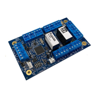
Address selection DIP switch. Configure the Interface’s address using the ADDRESS DIP
switch. Refer to “
DIP switch settings” on page 5.
Micro-B USB port (USB cable not supplied).
LOCK PWR 2-pin plug-in socket for lock power cable from a Network Access Controller.
Relay connections for two doors. Refer to “
Door lock relay wiring” on page 12. A suppression diode (such as 1N4004) must be fitted
across door locks.
Input terminals. See “Inputs” on page 12.
Earth terminal. Attach the ring terminal of the supplied earth lead. See “
Earthing” on page 18.
Two sets of Wiegand reader connections. See “Wiegand reader connections” on page
14.
TERM link for the RS-485 LAN/bus. See “Terminating the RS-485 LAN” on page 11.
4-pin plug-in socket for easy RS-485 cable connection to a Network Access Controller’s
BUS 1.
Heart beat LED. See “LED indications” on page 19.
RS-485 LAN/Bus
The TS1061 Dual Wiegand Interface can be connected to a ChallengerPlus
panel or Network Access Controller via the 4-pin RS-485 terminals (Figure 2 on
page 8 item 1).
Alternatively, the Interface can be connected to a Network Access Controller’s
BUS 1 via the 4-pin plug-in RS-485 socket (Figure 2 on page 8 item 14).
Using the plug-in RS-485 socket:
To easily connect the Interface to a Network Access Controller’s BUS 1, connect
a 4-way RS-485 cable (supplied) to the 4-pin plug-in RS-485 socket (Figure 2 on
page 8 item 14).
Refer to Figure 3 on page 10 for example connections of the 4-way RS-485 cable
from a Network Access Controller to the Interface (items B and D).