Channel indication CH1-CH2-CH3-CH4
Channel temperature CH1-CH2-CH3-CH4
F1 signal ON yellow LED (FAN1)
Channel reference label (*)
F2 signal ON yellow LED (FAN2)
ALR signal ON red LED (ALARM)
TRP signal ON red LED (TRIP)
(*) the label indication can be customised by the user in the options – labels settings screen, see page 25.
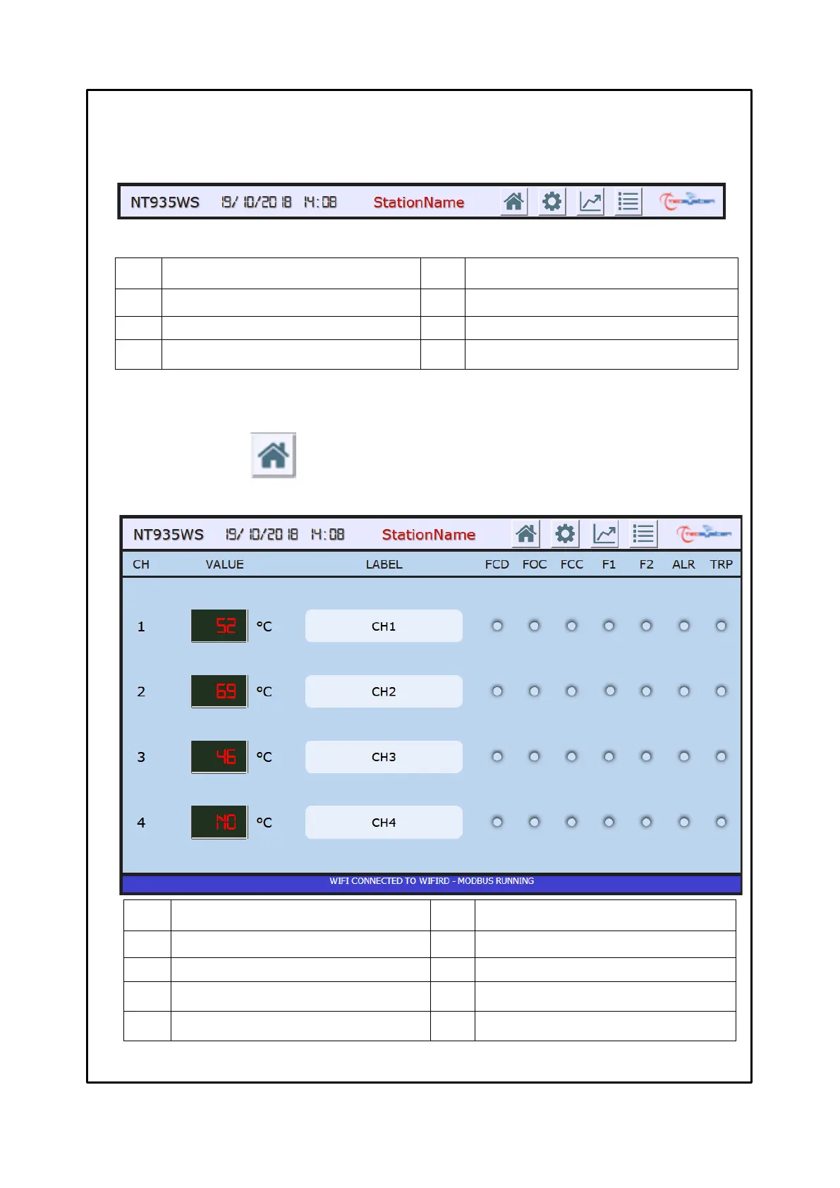
HOME SCREEN
The HOME screen shows the operating status of each channel, i.e.: the temperature detected by each channel, the FCD-
FOC-FCC sensor fault indications, activation of the F1-F2-ALARM-TRIP alarms.
WEB SERVER MANAGEMENT BAR
The web manager management bar allows the user to identify the cabin and to select the various screens.
The following information is shown in the management bar:
HOME screen selection key
SETTINGS screen selection key
GRAPHICS screen selection key
Station Name or monitored cabin (*)
EVENT LOG screen selection key
(*) The Station Name indication can be customised by the user in the options- labels settings screen, see page 25.
Pressing the selection keys 5-6-7-8 it is possible to access the various screens; the web manager will display only
one screen at a time.