3-2
Governed Idle Circuit: The TVT series engine uses a
governed idle system. In the low speed throttle position,
engine speed is being maintained by the governor NOT
the idle speed adjustment screw. The governed idle
system improves throttle response when the engine load
changes. The relatively small amount of fuel/air mixture
is supplied through the primary idle orifice location under
the idle mixing well welch plug. (Illust. 3-3)
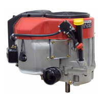
Idle Mixing Well: The idle mixing well of the carburetor
contains a series of metering holes. These metering holes
are the primary and secondary idle circuit as well as the
idle air bleed hole. Proper servicing of the carburetor
requires removal of the welch plug and cleaning of these
metering holes. (Illust. 3-4)
3-4
True Idle: The idle speed adjustment screw on governed
idle engines perform as a stop to prevent complete
closure of the throttle plate. This partial open throttle
position is required for good starting performance. The
idle adjustment screw is set 600 RPM lower than the
governed idle speed. (Found on microfiche card #30 or
the computer parts look-up systems.) See governed
speed adjustment procedure Chapter 4.
CAUTION: DUAL CARBURETORS MUST BE
PROPERLY SYCRONIZED. DO NOT ADJUST
IDLE SPEED SCREW WITHOUT PROPER
SYNCHRONIZATION.
Transfer/Intermediate Circuit: During Intermediate
engine operation or light loads, additional orifices are
uncovered in the idle mixing well, as the throttle shutter
opens. The fuel being released from these jets is already
pre-mixed (atomized) with air prior to entering the air
stream in the venturi of the carburetor. When the fuel
enters the air stream it further mixes with the air which
maximizes combustibility.
IDLE
MIXING
WELL
3-5
IDLE
MIXING WELL
High Speed Circuit: During HIGH-SPEED engine
operation, the throttle shutter is opened beyond the idle/
transfer discharge ports. Air is flowing through the
carburetor(s) at a high rate. The venturi, which decreases
the size of the air passage through the carburetor, causes
the airflow to further accelerate. This rapidly moving air
creates a low-pressure area at the main nozzle (Emulsion
Tube) discharge opening.
Using air that is channeled to the emulsion tube through
the main nozzle air bleed, a mixture of fuel and air is
drawn up the emulsion tube.
The addition of air creates an atomized mixture before
being discharged into the venturi. Fuel flow is created
by the difference in the atmospheric air pressure on the
fuel in the carburetor bowl and the main nozzle opening.
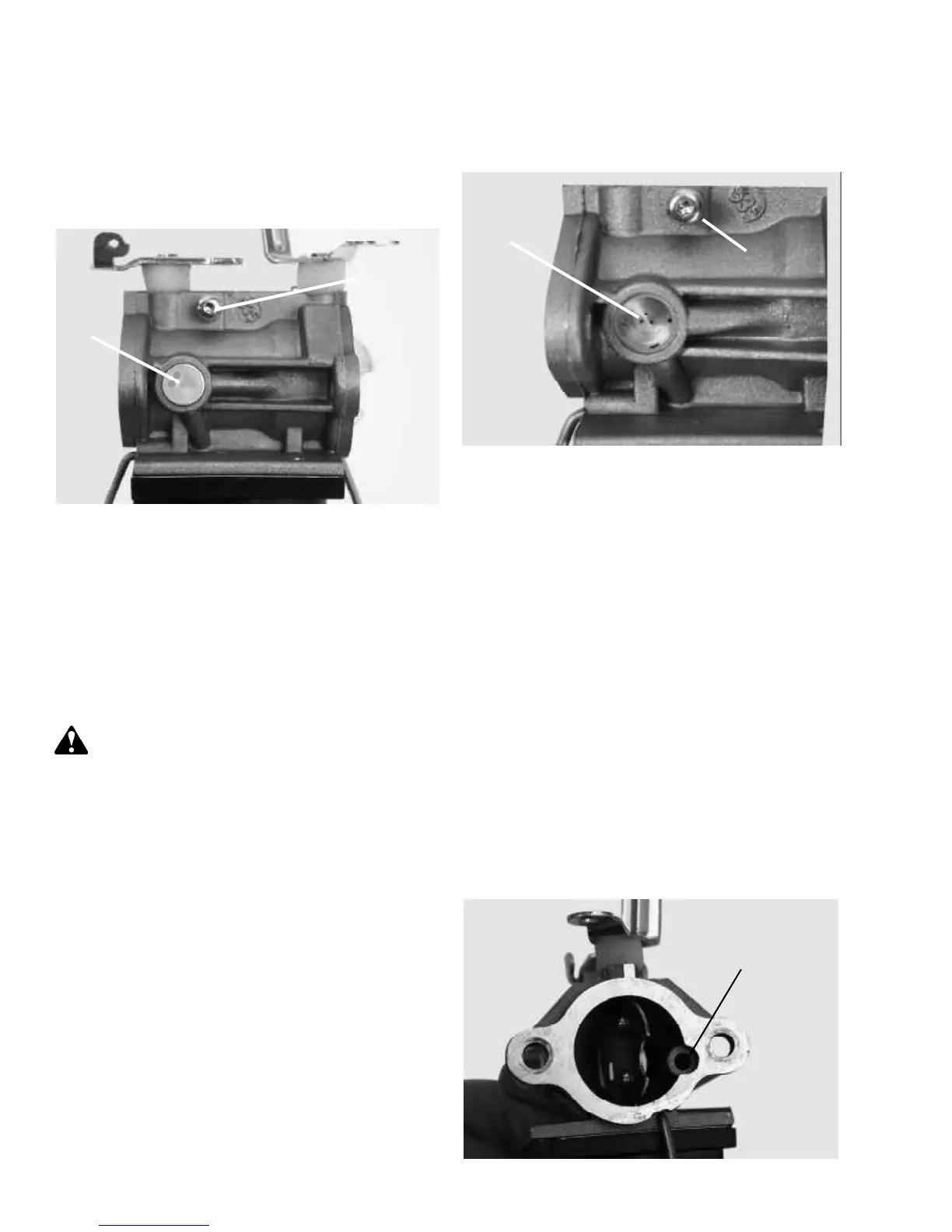
Atmospheric Vent: For the fuel to flow out of the
carburetor, the bowl must be vented to atmospheric
pressure. The internal vent is located at the 4 o’clock
position from the choke end of the carburetor. (Illust.
3-5) This passage should be checked for blockage if
engine performance is in question.
3-3
IDLE SPEED
ADJUSTMENT
SCREW
ATMOSPHERIC
VENT
IDLE SPEED
ADJUSTMENT
SCREW
 Loading...