7-9
RINGS
Specification English Std. Metric
Piston Ring .002-.005 Top .051-.127 Top
Side Clearance .001-.004 Center .025-.102 Center
.001-.004 Bottom .025-.102 Bottom
Piston Ring .007-.015 Top .178-.381-Top
End Gap .013-.021 Center .330-.533 Center
.005-.013 Bottom .127-.330 Bottom
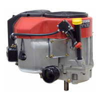
After the cylinder bore diameter has been checked and
is acceptable to rebuild, the ring end gap should be
checked using new rings. Place a new compression ring
squarely in the center of the ring travel area. Use the
piston upside down without rings to push the ring down
in the cylinder. (Illust. 7-26) Measure the gap with a feeler
gauge. (Illust. 7-27) The ring end gap must be within
specification to have adequate oil control.
7-26
7-27
NOTES:
1. A difference exists in piston ring end gaps between
the upper and center compression rings. Check the
specification table for the appropriate ring end gap.
2. Use a ring expander (Tecumseh tool part number
670117) to replace the piston rings. Do not spread
the rings too wide or breakage will result.
3. If installing new rings on a used piston, piston ring
side clearance must be checked.
4. Always replace the rings in sets.
5. Always install the piston and ring assembly in the
cylinder bore with the ring end gaps staggered.
6. When installing new rings in a used cylinder, the
cylinder wall should be de-glazed using a
commercially available de-glazing tool or hone with
380 grit stones. The crosshatch pattern should be
35-45 degree’s.
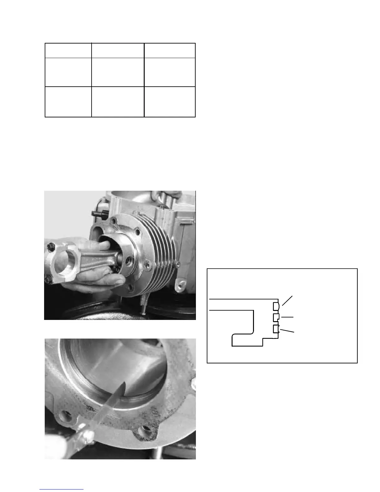
The emission ring set used on the TVT consists of two
compression rings and an oil control ring. The top
compression ring is barrel faced on the outside. This
ring can be installed with either side up. The second
compression ring will have an outside notch, which must
face down or towards the piston skirt. The oil control
ring can be installed with either side up. (Illust. 7-28)
7-28
EMISSION RINGS
1ST COMPRESSION RING
2ND COMPRESSION RING
3RD OIL CONTROL RING
 Loading...