7-1
CHAPTER 7. INTERNAL ENGINE AND DISASSEMBLY
GENERAL INFORMATION
This chapter covers the cylinder block, piston and rod
assemblies, cylinder heads, crankshaft, camshaft, valve
train, breather, cylinder cover, flywheel, and lubrication
systems. The internal governor systems are covered in
Chapter 4.
The TVT series engines are made using aluminum alloy
die cast around a cast iron cylinder liners.
LUBRICATION SYSTEMS
The TVT series engine uses an automotive type rotary
pump. Oil is drawn up to the pump from the pump inlet
screen area in the mounting flange cover/sump. Oil is
then pressurized and directed through the oil filter (if
equipped). This engine differs from OHV single cylinder
models in that the flange cover/sump bearings are also
pressure lubed.
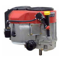
From the oil filter the oil flows through the feed passages
to all crankcase bearings starting with the lower cam
and lower main bearing. The crankshaft has an undercut
around the bearing surface, which aligns with the oil feed
galley passage. The drilling of the crankshaft creates
the passage to the connecting rod bearings and the upper
main bearing. The upper camshaft bearing is fed oil by a
passage from the upper main bearing. See flow passage
(Illust. 7-1)
7-1
DISASSEMBLY PROCEDURE
1. Disconnect the high-tension leads from the spark
plugs. Remove the spark plugs. Evaluate each of
the spark plug(s) condition, for tips on areas
specifically in need of repair.
2. Drain the oil from the crankcase. Drain or shut off
the fuel supply and disconnect the fuel line at the
pump or carburetors.
3. Remove the negative battery lead. Remove the
positive cable to the starter. Unplug the charging/
ignition shut-off wires and the fuel shut-off solenoid
wires.
4. Remove the electric starter motor from the engine.
5. Disconnect the exhaust system from the engine.
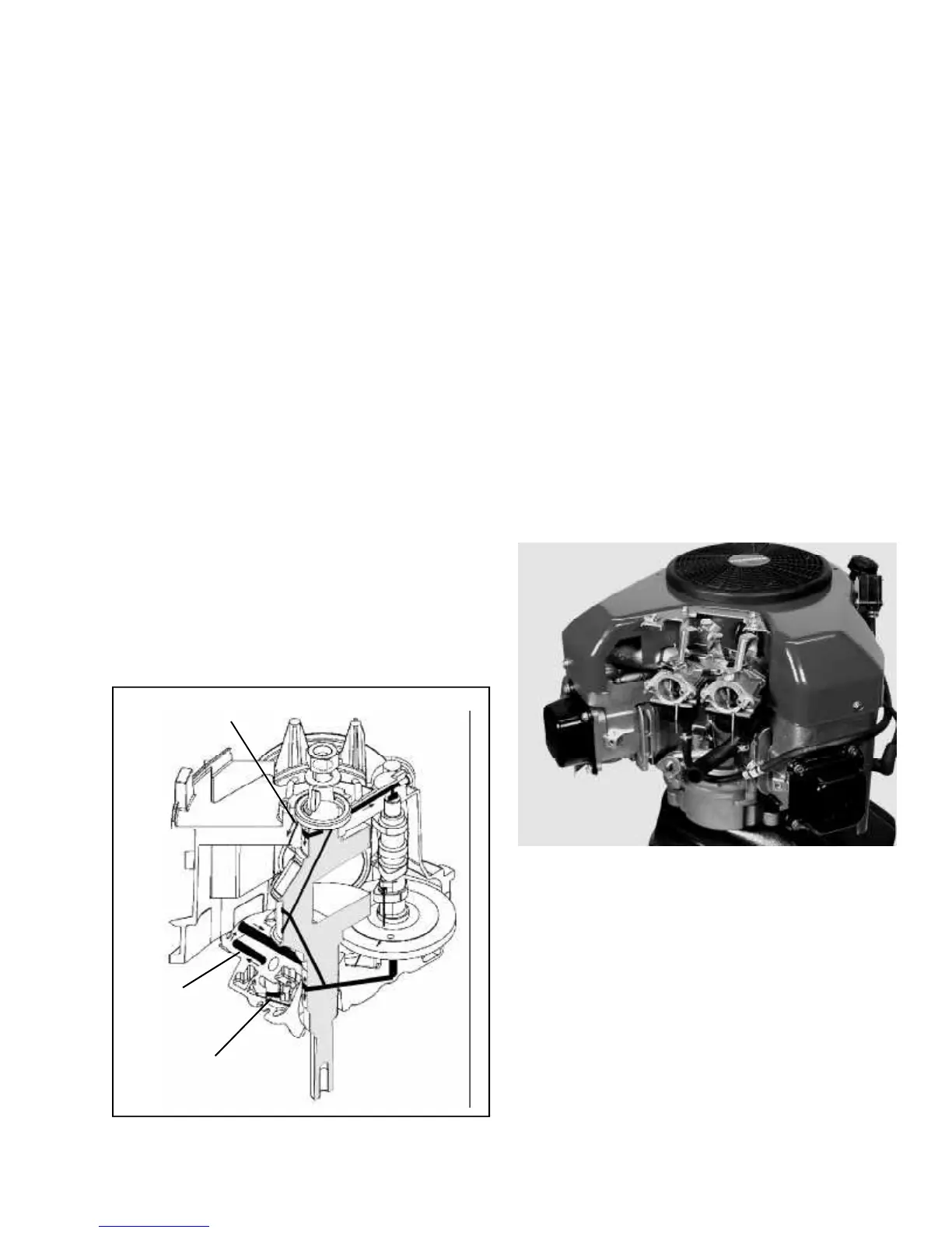
6. Remove the air cleaner assembly. (Cover, Filters,
deflector, control cover and air filter body).
(Illust. 7-2)
7. Remove the flywheel-rotating screen.
8. Remove the blower housing by first removing the
screw holding the dipstick tube and fuel pump to the
blower housing. Remove the remaining three bolts
holding on the blower housing.
9. Unplug the ignition ground wire from the terminal on
top of the ignition modules and remove the ignition
modules.
10. Locate the piston at top dead center (TDC) on the
number one cylinder (lowest cylinder) at the
compression stroke for easier valve train service.
7-2
OIL PICK UP
OIL RETURN
TO OIL FILTER
 Loading...