Technology Solutions
Instruction Manual
Tek-Flux 1400A
www.tek-trol.com
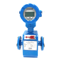
4.5.5 Digital Output Connection as Relay
Commonly, the relay needs E as 12V or 24V. D is an extended diode, most middle
relays now have this diode inside. If not have, the user can connect one outside.
4.6 Simulation Signal Output and Calculation
4.6.1 Simulation Signal Output
There are two signal systems: 0 to 10 mA and 4 to 20 mA. The user can select from the
parameter setting.
The inner simulation signal output is 24V under 0 to 20 mA. It can drive 750Ω
resistance. The percent flux of simulation signal output is:
I
o
=
× +
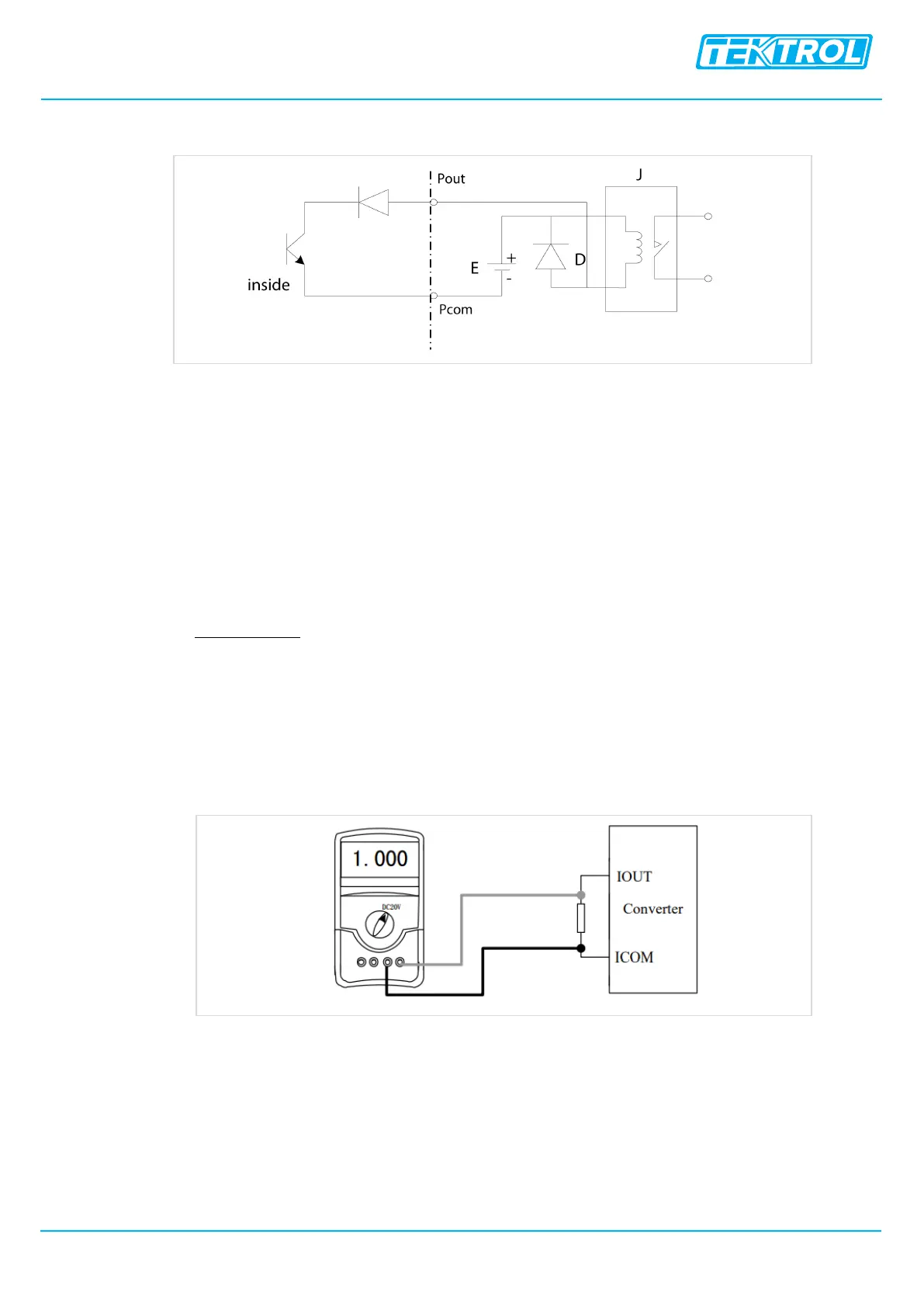
4.6.2 Simulation Signal Output Adjust
• The converter adjusts the Preparative
When the converter has been running for 15 minutes, the inside of the converter
becomes stabilized. The preparative is 0.1% ampere meter or 250Ω, 0.1% voltage
instrument
• Current Zero is Correct
When the converter is in parameter setting, select to “Analog Zero” and press enter.
The standard of signal fountain is set to “0.”. Adjust the parameter and make sure the
ampere meter is 4 mA (±0.004 mA).
 Loading...