EasyManuals Logo

TEKTROL Tek-Flux 1400A Series User Manual

TEKTROL Tek-Flux 1400A Series
31 pages
To Next Page IconTo Next Page
To Previous Page IconTo Previous Page
Page #19 background imageLoading...
Page #19 background image
Technology Solutions
Instruction Manual
Tek-Flux 1400A
www.tek-trol.com
17
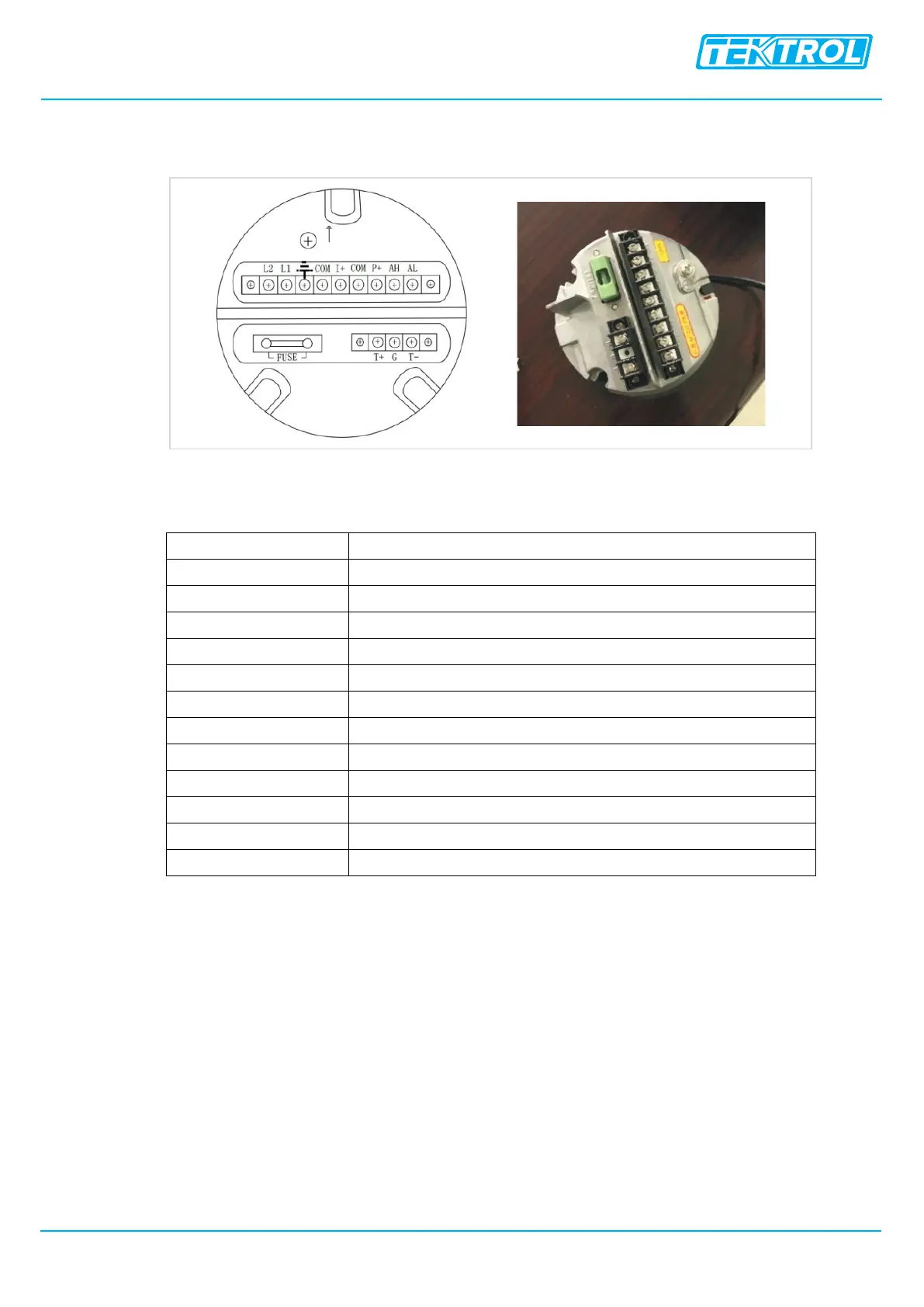
4.3.2 Power Supply Wiring
Wiring for direct mount transmitter
The above figure shows the wiring terminal board of a Direct Mounted Transmitter
I+
Output Current for Flow Measurement
COM
Output Current (Ground) for Flow Measurement
P+
Frequency (Pulse) Output for Bi-directional Flow
COM
Frequency (Pulse) Output (Ground)
AL
Alarm Output for Low Limit
AH
Alarm Output for Upper Limit
COM
Alarm Output (Ground)
FUSE
Fuse for Power Supply
T
+Communication Input Signal
T
-Communication Input Signal
G
RS232 Communication Ground
L
1
220V(24V) Power Supply
L
2
220V(24V) Power Supply

Questions and Answers:

Question and Answer IconNeed help?

Do you have a question about the TEKTROL Tek-Flux 1400A Series and is the answer not in the manual?

TEKTROL Tek-Flux 1400A Series Specifications

General IconGeneral
BrandTEKTROL
ModelTek-Flux 1400A Series
CategoryMeasuring Instruments
LanguageEnglish